Method and system for accessing video conference through network live broadcast
A video conferencing and webcasting technology, which is applied in the field of video communication, can solve the problems of wasting hardware resources, limited number of concurrency, and inability to realize document sharing, etc., and achieves the effect of simple and fast operation, and improved stability and reliability
- Summary
- Abstract
- Description
- Claims
- Application Information
AI Technical Summary
Problems solved by technology
Method used
Image

Examples
Embodiment 2
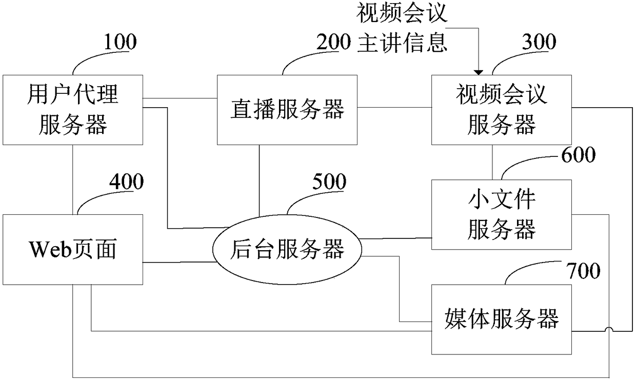
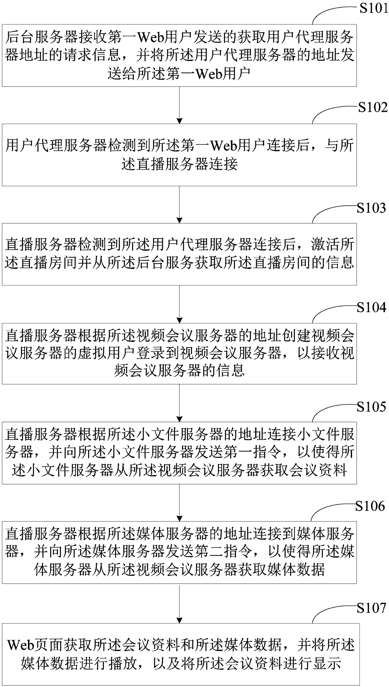
[0079] Corresponding to the structural diagram of each part of the above-mentioned webcast access video conferencing system, this embodiment discloses a method for webcast access to a video conference. see figure 2 , which shows a schematic flow diagram of an embodiment of a method for accessing a video conference through a webcast, and is described in detail as follows:
[0080] Step S101, the background server receives the request information for obtaining the address of the user agent server sent by the first web user, and sends the address of the user agent server to the first web user, so that the first web user can obtain the address of the user agent server according to the The address of the user agent server to connect to the user agent server.
[0081] Wherein, the first Web user is the first Web user who logs into the live broadcast room within a preset time period.
[0082] Optionally, step S101 specifically includes the following steps:
[0083] After the back...
Embodiment 3
[0129] In order to facilitate the understanding of the method of accessing the video conference through live webcasting, the present invention also provides specific steps for realizing the access to the video conference. see Figure 4 , which shows a schematic flowchart of another embodiment of a method for accessing a video conference through a webcast, and is described in detail as follows:
[0130] Step S301: The web page is connected to the background server first, and the background server performs authentication processing on the user. After the authentication is passed, the address of the user agent server is returned to the web user in combination with the IP address of the web user and the load pressure of the proxy server, and is stored in the background database. Add a Token in.
[0131] Step S302: The web page is connected to the user agent server, and the user agent server activates the Token to the background server and obtains the address of the live broadcast...
PUM
 Abstract
Description
Claims
Application Information
 - R&D
- Intellectual Property
- Life Sciences
- Materials
- Tech Scout
- Unparalleled Data Quality
- Higher Quality Content
- 60% Fewer Hallucinations
Browse by: Latest US Patents, China's latest patents, Technical Efficacy Thesaurus, Application Domain, Technology Topic, Popular Technical Reports.
© 2025 PatSnap. All rights reserved.Legal|Privacy policy|Modern Slavery Act Transparency Statement|Sitemap|About US| Contact US: help@patsnap.com