Heat dissipation structure for communication terminal

A communication terminal and heat dissipation structure technology, which is applied in the direction of cooling/ventilation/heating transformation, etc., can solve the problems of poor cooling effect, high energy consumption, complex structure, etc., and achieve the effects of energy saving, high heat dissipation efficiency, and reduced wind resistance

Active Publication Date: 2018-07-17
湖南艾尔时钟表有限公司
View PDF3 Cites 3 Cited by
  • Summary
  • Abstract
  • Description
  • Claims
  • Application Information

AI Technical Summary

Problems solved by technology

Common cooling methods include water cooling and air cooling. Water cooling has a good cooling effect, but its structure is complex and consumes a lot of energy. Air cooling has a simple structure and low power, but its cooling effect is poor.
In most cases, air cooling can cool the communication terminal, but in the case of external high temperature or high-intensity operation of the equipment, air cooling cannot meet the cooling requirements of the equipment

Method used


Image

  • Heat dissipation structure for communication terminal
  • Heat dissipation structure for communication terminal

Examples


Embodiment Construction

[0020] Further detailed explanation through specific implementation mode below:

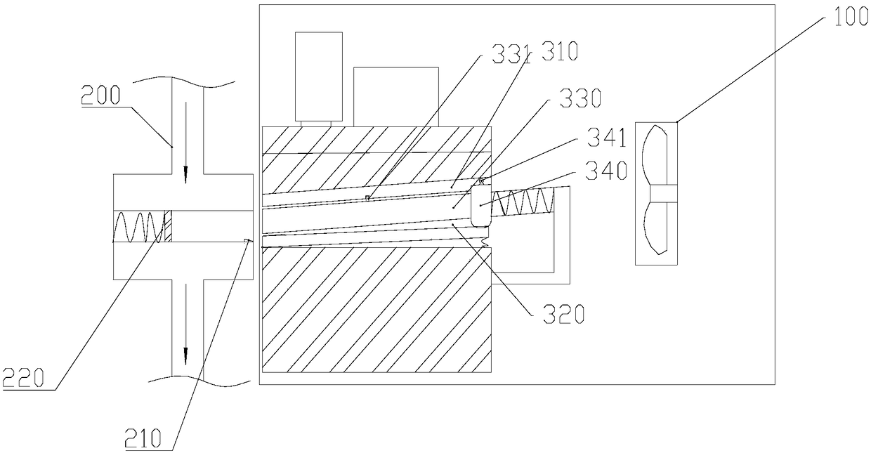
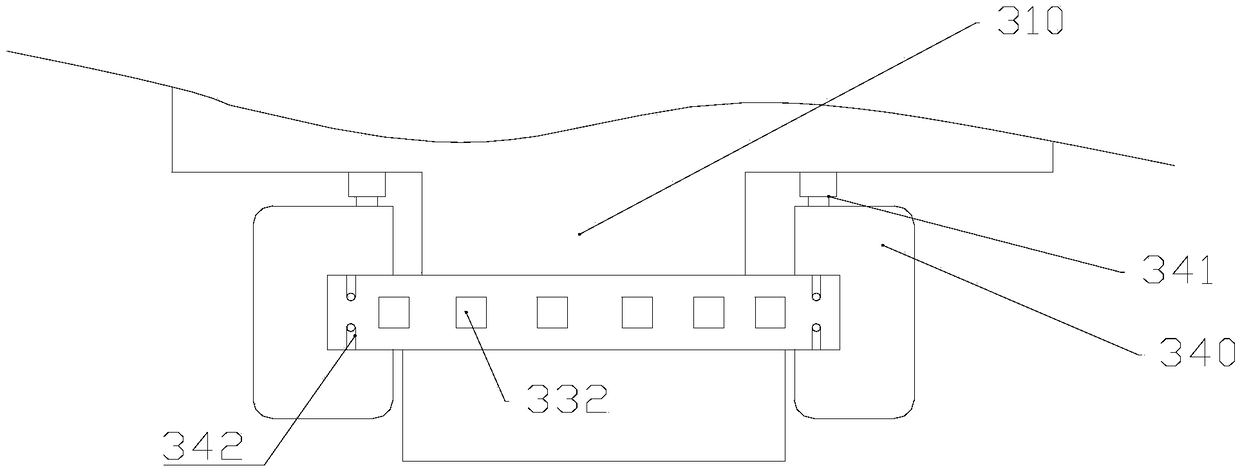
[0021] The reference signs in the drawings of the description include: fan 100, water-cooling pipe 200, trigger switch 210, half-stroke spring 220, heat transfer plate 310, guide rail 320, heat dissipation plate 330, contact protrusion 331, heat dissipation through hole 332, expansion piece 340 , a top block 341 , and a cooling channel 342 .

[0022] The embodiment is basically as attached figure 1 Shown: the heat dissipation structure of the communication terminal, including the casing, the fan 100, the water cooling mechanism and the heat dissipation mechanism, the fan 100 and the heat dissipation mechanism are arranged inside the casing, the water cooling mechanism is arranged outside the casing, and the heat dissipation mechanism is located in the air outlet direction on the left side of the fan 100 . The heat dissipation mechanism includes a heat transfer plate 310, a guide rail 320, a hea...


PUM


Abstract

The invention relates to a heat dissipation structure, in particular to a heat dissipation structure for a communication terminal. The heat dissipation structure comprises a shell, a fan, a water cooling mechanism and a heat dissipation mechanism, wherein the fan and the heat dissipation mechanism are arranged in the shell; the water cooling mechanism is arranged out of the shell; the heat dissipation mechanism is located in an air outlet direction of the fan and comprises a heat transfer plate, a guide rail, a heat dissipation panel and an expansion member; one end of the guide rail is hingedwith an outer wall of the shell and a spring is arranged between the other end of the guide rail and an inner wall of the shell; the heat dissipation panel is connected to the guide rail in a slidingmanner; a reset spring is arranged between the heat dissipation panel and the guide rail; a heat dissipation through hole is formed in the heat dissipation panel; an expanding gas is arranged in theexpansion member; the material of the expansion member is an elastic material; an opening out of which the heat dissipation panel slips is formed in the front end of the shell; the water cooling mechanism comprises a water cooling pipe and a water cooling pump; a water cooling groove into which the heat dissipation panel slips is formed in the water cooling pipe; and a trigger switch for startingthe water cooling pump is arranged in the water cooling groove. The invention provides a heat exchange structure with a relatively good cooling effect.

Description

technical field [0001] The invention relates to a heat dissipation structure, in particular to a heat dissipation structure of a communication terminal. Background technique [0002] Communication terminal is a direct tool for people to enjoy different information applications, and it undertakes various tasks such as providing users with a good user interface, completing required business functions, and accessing communication networks. Some of these large communication terminals emit a lot of heat when they are in operation. How to ensure the stable operation of communication terminals, temperature control is a key technology. [0003] A cooling structure is installed in a common communication terminal to make the equipment operate normally. Common cooling methods include water cooling and air cooling. Water cooling has a good cooling effect, but its structure is complex and consumes a lot of energy. Air cooling has a simple structure and low power, but its cooling effect...

Claims


Application Information

Patent Timeline
Patent Type & Authority Applications(China)
IPC IPC(8): H05K7/20
Inventor 秦波
Owner 湖南艾尔时钟表有限公司
Why Eureka
Try Eureka