Clutch with pressed-in drive ring

A clutch and tooth technology, applied in the field of clutches of motor vehicles, can solve problems such as reducing assembly complexity, and achieve the effects of reducing complexity, increasing operational reliability, and stabilizing torque transmission

Active Publication Date: 2021-05-14
SCHAEFFLER TECH AG & CO KG
View PDF10 Cites 0 Cited by
  • Summary
  • Abstract
  • Description
  • Claims
  • Application Information

AI Technical Summary

Problems solved by technology

[0006] Against the background of these references, the technical problem to be solved by the present invention is to overcome the disadvantages of the prior art and, in particular, to disclose a technical device which enables a space-saving connection of the drive ring to the counter pressure plate of the clutch, And at the same time reduce the complexity of assembly

Method used


Image

  • Clutch with pressed-in drive ring
  • Clutch with pressed-in drive ring
  • Clutch with pressed-in drive ring

Examples


Embodiment Construction

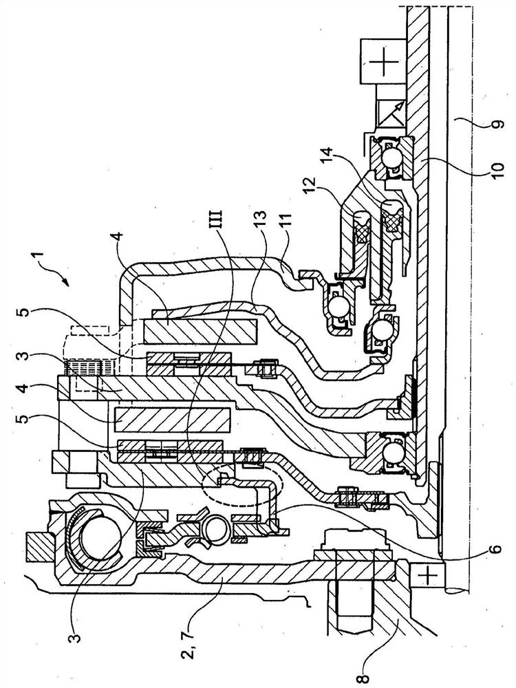
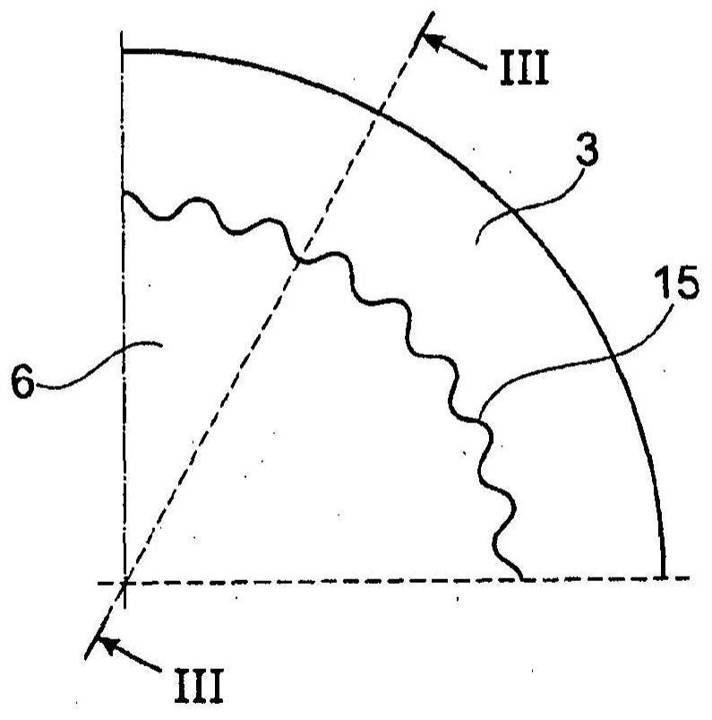
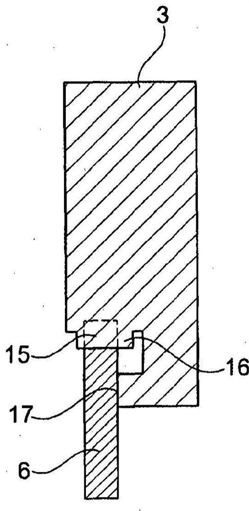
[0038] figure 1A clutch 1 for a motor vehicle is shown. In this case, the connection part 2 is connected to the counterplate 3 . The clutch 1 in the case of the present invention is designed as a double clutch and therefore has a plurality of counterplates 3 . By means of one or more pressure plates 4 (also referred to as pressure plates), an axial force is exerted on the clutch disc 5 such that torque can be transmitted. The drive toothed ring 6 is arranged between the interface part 2 and the counterplate 3 .

[0039] In this example, the interface part 2 is designed as a flywheel 7 on the engine side in the form of a dual-mass flywheel. A drive ring 6 is provided for accommodating the counterpressure disk 3 arranged on the transmission side next to the engine-side flywheel 7 between the engine-side flywheel 7 and the clutch plate.

[0040] The clutch 1 according to the invention transmits torque between the crankshaft-fixed part 8 and the transmission-fixed solid shaft ...


PUM


Abstract

The invention relates to a clutch (1) for a motor vehicle comprising an interface part (2) drivable by an internal combustion engine, a counter-pressure plate ( 3) and a drive gear ring (6) separate from at least said counter pressure plate (3), said drive gear ring being designed to transmit torque from said interface part (2) to said counter pressure plate (3), Wherein, the driving gear ring (6) is pressed and connected with the counter pressure plate (3). The invention also relates to a drive train comprising a clutch according to the invention and an interface part designed as a dual mass flywheel. The invention also relates to a method for assembling a clutch according to the invention, characterized in that the drive toothed ring (6) is pressed into the material of the counterplate (3) to produce a form-fit connection.

Description

technical field [0001] The invention relates to a clutch for a motor vehicle, such as a car, truck or other commercial vehicle, comprising an interface part (Schinttstellebauteil), a counter pressure plate and a drive ring, the interface part being able to be driven by an internal combustion engine and e.g. is a single-mass flywheel or a dual-mass flywheel, the counterplate is co-designed / provided with the pressure plate for clamping the clutch disc, the drive ring is at least separate from the counterplate, and the drive ring is designed / provided for torque transfer from the interface member / Transfer to backplate. Background technique [0002] Published patent application DE 10 2014 216 277 A1 discloses a friction clutch which can be connected in a rotationally fixed manner to an interface part designed as a dual-mass flywheel. [0003] Motor vehicle drive trains with a compressed single clutch are likewise known from the prior art. In this case, the drive toothed ring i...

Claims


Application Information

Patent Timeline
Patent Type & Authority Patents(China)
IPC IPC(8): F16D13/70
CPCF16D13/70F16D2021/0669F16D2021/0615F16D25/10F16D2300/12F16D1/10F16D2001/103F16D1/101F16D25/082F16D21/06F16D2021/0684
Inventor 卡尔-路德维格·基米希亚历山大·康斯坦丁诺夫
Owner SCHAEFFLER TECH AG & CO KG
Why Eureka
Try Eureka