Bearing device for wheel, method of assembling bearing device for wheel, assembly constructed from bearing device for wheel and from drive shaft, and method of assembling assembly

A technology of a bearing device and an assembly method, which is applied in the direction of bearings, axles, wheels, etc., can solve the problems of not being able to press the outer joint parts, the difficulty of stable pressing, and the small area of ​​the pressing part, so as to eliminate shaking and stably press in operation, and the effect of improving reliability

Inactive Publication Date: 2013-02-13
NTN CORP
View PDF1 Cites 0 Cited by
  • Summary
  • Abstract
  • Description
  • Claims
  • Application Information

AI Technical Summary

Problems solved by technology

Therefore, the outer end surface of the outer joint member cannot be pressed against, and stable press-fitting is difficult.
In addition, when a pressing force is applied to the shaft end surface of the outer joint member of the outboard constant velocity universal joint, the area of ​​the pressing portion is small, the application of pressing force (pressing force) is unstable, and the pressing force is applied It will cause damage to the internal components (inner wheel, box body, ball) of the constant velocity universal joint

Method used


Image

  • Bearing device for wheel, method of assembling bearing device for wheel, assembly constructed from bearing device for wheel and from drive shaft, and method of assembling assembly
  • Bearing device for wheel, method of assembling bearing device for wheel, assembly constructed from bearing device for wheel and from drive shaft, and method of assembling assembly
  • Bearing device for wheel, method of assembling bearing device for wheel, assembly constructed from bearing device for wheel and from drive shaft, and method of assembling assembly

Examples


Embodiment Construction

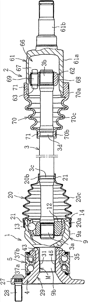
[0077] Below, according to Figure 1~Figure 10 The embodiment of the present invention is explained. figure 1 Represents a combination of a wheel bearing device and a drive shaft. The wheel bearing device has a constant velocity universal joint 1 on the outboard side, a constant velocity universal joint 2 on the inboard side, and these constant velocity universal joints 1, 2 Connected shaft 3. In this case, in the outboard side, the hub 4, the multi-row wheel bearing 5, and the constant velocity universal joint 1 are connected to form a wheel bearing device. When assembled on a car or other vehicle, the outer side of the vehicle is called the outboard (left side of the figure), and the one that constitutes the inner side of the vehicle when assembled on a car or other vehicle is called the inner side of the vehicle (right side of the figure) ).

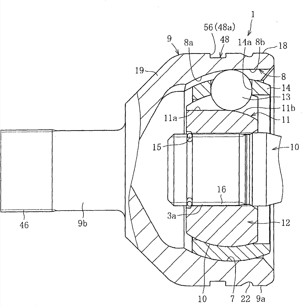
[0078] Constant velocity universal joint 1 on the outboard, such as figure 2 Shown are: the outer joint member 9 with a plurality o...


PUM


Abstract

The present invention provides a wheel bearing device, a method of assembling the wheel bearing device, an assembly configured by the wheel bearing device and a drive shaft, and a method of assembling the assembly, in which the wheel bearing device eliminates a nut tightening operation, is capable of reducing costs, and has a projection and recess mating structure that can firmly connect an outer joint member and a hub. Axial direction load is applied to a stepped surface 56 provided on an outer diameter surface of an outer joint member. A projection that extends in the axial direction and is provided on one of a stem shaft 9b of the outer joint member and an inner diameter surface of a hole section 29 of a hub 4 is press-fitted into a partner member along the axial direction, As a result, a recess that is in close contact with the projection over an overall mating contact area 45 is formed in the partner member, thereby configuring a projection and recess mating structure M.

Description

Technical field [0001] The present invention relates to a bearing device for a wheel, a method for assembling the bearing device for a wheel, an assembly composed of a bearing device for a wheel and a drive shaft, and an assembly method for the assembly. Background technique [0002] Transmit the power from the engine to the drive shaft that drives the wheels, such as Picture 11 As shown, there is a fixed type constant velocity universal joint 104 in which the outboard side (the outer side of the vehicle is formed when assembled on the vehicle) by an intermediate shaft that is not shown in the figure, and the inboard side (the side of the vehicle is formed when assembled on the vehicle. The structure of the sliding type constant velocity universal joint (not shown) on the inner side. The constant velocity universal joint 104 on the outboard side is coupled to a hub 102 rotatably supported by a wheel bearing device. [0003] The third-generation wheel bearing device is provided wit...

Claims


Application Information

Patent Timeline
Patent Type & Authority Patents(China)
IPC IPC(8): B60B27/00B60B35/12B60B35/18F16C19/18F16D1/08F16D3/2237F16D3/224B60B35/14F16D1/06F16D3/20F16D3/205F16D3/2245
CPCF16C19/186F16D3/2237F16D2003/22326F16D1/072B60B2900/112B60B27/0084B60B2310/54B60Y2200/11B60B27/0094F16D3/224B60B2310/305F16C19/184B60B35/18B60B2900/111B60B35/128B60B27/0042B60B27/0026B60B2310/316F16D2300/10F16D1/0858B60B2360/102B60B27/0005B60B2310/208F16D2250/00F16C2326/02Y02T10/86Y10T29/49682F16C19/18F16D3/20
Inventor 中川亮浅野祐一小泽仁博
Owner NTN CORP
Why Eureka
Try Eureka