Pit pump long-distance-suspended pump pipe swinging concreting construction technology for high-rise buildings

A technology for pouring concrete and high-rise buildings. It is used in construction, building structure, and building material processing. It can solve problems affecting construction safety and formwork installation quality, limitations on the height and amplitude of automobile pumping, and weakening of steel bars and concrete. It can improve the overhead span, ensure construction quality and safety, and ensure the effect of structural quality.

Inactive Publication Date: 2014-12-17
GUANGXI CONSTR ENG GROUP THE THIRD CONSTR ENG +1
View PDF3 Cites 5 Cited by
  • Summary
  • Abstract
  • Description
  • Claims
  • Application Information

AI Technical Summary

Problems solved by technology

The main problems of the ground pump concrete delivery technology are as follows: 1. The pump pipe of the ground pump does not move much. Generally, the pipe can only cover 5~8 square meters at a time. Large-area concrete pouring requires multiple installations and dismantling of the moving pump pipe, which is labor-intensive. ;, After the pump pipe of the ground pump is connected to the floor, the horizontal pump pipe needs to be raised on the formwork and steel bar surface of the floor to be poured to transport the concrete to the pouring surface, and the horizontal pump pipe is usually lifted by a steel pipe support frame or a ti

Method used


Image

  • Pit pump long-distance-suspended pump pipe swinging concreting construction technology for high-rise buildings
  • Pit pump long-distance-suspended pump pipe swinging concreting construction technology for high-rise buildings
  • Pit pump long-distance-suspended pump pipe swinging concreting construction technology for high-rise buildings

Examples


Example Embodiment

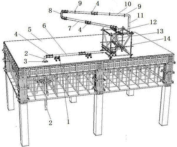
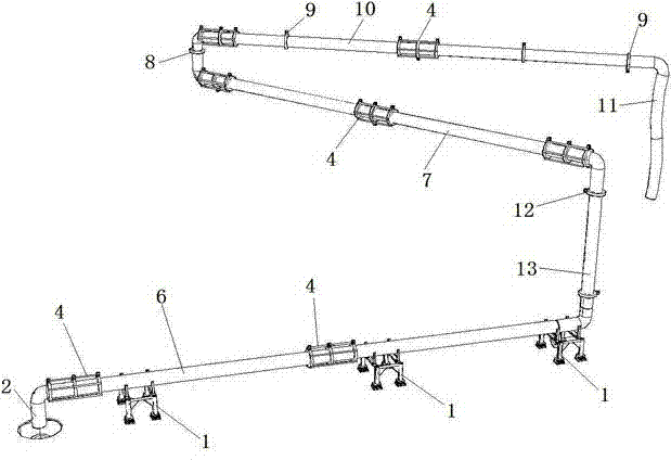
[0023] Such as figure 1 , figure 2 As shown, the construction process of long-distance suspension and swing pouring concrete of the pump tube of the high-rise building of the present invention includes the following construction steps:

[0024] (1) Install the pump pipe through the floor slab 2: When installing the floor template 5, reserve the reserved port 3 of the pump pipe 2 through the floor slab at the position of the pump pipe 2 through the floor slab in the pump pipe layout diagram, and the pump pipe through the floor slab 2 Use reserved ground anchors to fix in four directions, and the height of the extended floor is generally the thickness of the plate plus 150mm, which is convenient for the installation of the horizontal pump pipe 6. The bottom end of the pump pipe 2 through the floor is connected to the ground pump, and the top passes through The reserved opening 3 of the floor formwork 5 extends to the upper side of the floor formwork 5 to be poured.

[0025] (2) Inst...


PUM


Abstract

The invention discloses pit pump long-distance-suspended pump pipe swinging concreting construction technology for high-rise buildings, and relates to building construction technology. The technology comprises the following construction steps of: 1, installing a pump line passing through a floorboard; 2, installing a horizontal pump pipe, wherein the front end of the horizontal pump pipe is connected to the pump pipe passing through the floorboard while the rear end of the horizontal pump pipe is connected to a working face movable pump pipe, the horizontal pump pipe is supported by a shake-removing support device, and the pipe joint of the horizontal pump pipe is sleeved with a stiffening sleeve; 3, installing the working face movable pump pipe, wherein a 360-degree rotational movable joint I is connected between the working face movable pump pipe and the horizontal pump pipe, and the pipe joint of the working face movable pump pipe is also sleeved with a joint stiffening sleeve; 4, concreting, wherein concrete is poured to floorboard templates through the pump pipe passing through the floorboard, the horizontal pump pipe and the working face movable pump pipe. According to the technology provided by the invention, disturbance of impact force of the pump pipe to reinforcing bars, templates and poured concrete can be eliminated in a concrete pumping process, and large area of concrete can be poured at one time.

Description

technical field [0001] The invention relates to a building construction technology, in particular to a construction technology for long-distance suspension and swinging pouring of ground pump pipes in high-rise buildings. Background technique [0002] In the current concrete construction of high-rise buildings, ground pump concrete delivery technology has been widely used, especially in the floor concrete construction of high-rise and super high-rise buildings, ground pump concrete delivery is an indispensable technology. The main problems of the ground pump concrete delivery technology are as follows: 1. The pump pipe of the ground pump does not move much. Generally, the pipe can only cover 5~8 square meters at a time. Large-area concrete pouring requires multiple installations and dismantling of the moving pump pipe, which is labor-intensive. ;, After the pump pipe of the ground pump is connected to the floor, the horizontal pump pipe needs to be raised on the formwork and...

Claims


Application Information

Patent Timeline
IPC IPC(8): E04G21/04
Inventor 梁德初周志荣黄澎覃宗志李家雨梁壹程
Owner GUANGXI CONSTR ENG GROUP THE THIRD CONSTR ENG
Why Eureka
Try Eureka