Crushing machine

A crusher and three-stage crushing technology, applied in the direction of solid separation, filter screen, grid, etc., can solve the problems of poor crushing effect, inconvenient operation, high cost, etc., and achieve the effect of improving the crushing effect and saving costs

Active Publication Date: 2018-07-20
涌纬集团股份有限公司
View PDF3 Cites 4 Cited by
  • Summary
  • Abstract
  • Description
  • Claims
  • Application Information

AI Technical Summary

Problems solved by technology

[0004] The purpose of the present invention is to provide a crusher to solv

Method used


Image

  • Crushing machine
  • Crushing machine

Examples


Embodiment 1

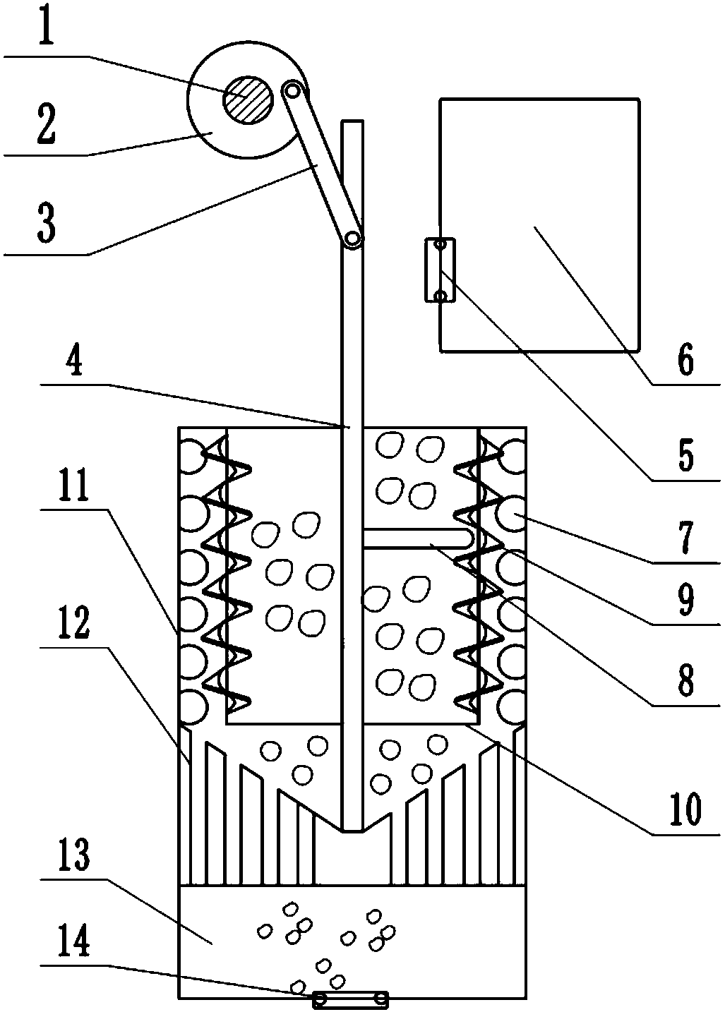
[0020] Such as figure 1 As shown, a crusher includes a drive unit, the drive unit includes a motor 1, the output shaft of the motor 1 is connected to a disc 2, the disc 2 is hinged to a connecting rod 3, and the connecting rod 3 is hinged to a sliding rod 4 that can move up and down. The upper part of the slide bar 4 is fixedly connected with a threaded rod 8, one side of the drive unit is provided with a feed box 6, one side of the feed box 6 is provided with a one-way feed door 5, and the bottom of the feed box 6 is provided with a crushing unit. The unit includes a primary crushing part, a secondary crushing part and a tertiary crushing part. The primary crushing part includes a crushing box. The crushing box includes an outer wall 11 and an inner wall 10 rotatably connected to the outer wall. The inner wall 10 is a hollow structure. There is an opening for the material in the feed box 6 to enter, and the lower end of the inner wall 10 is provided with a port for the slide ...

Embodiment 2

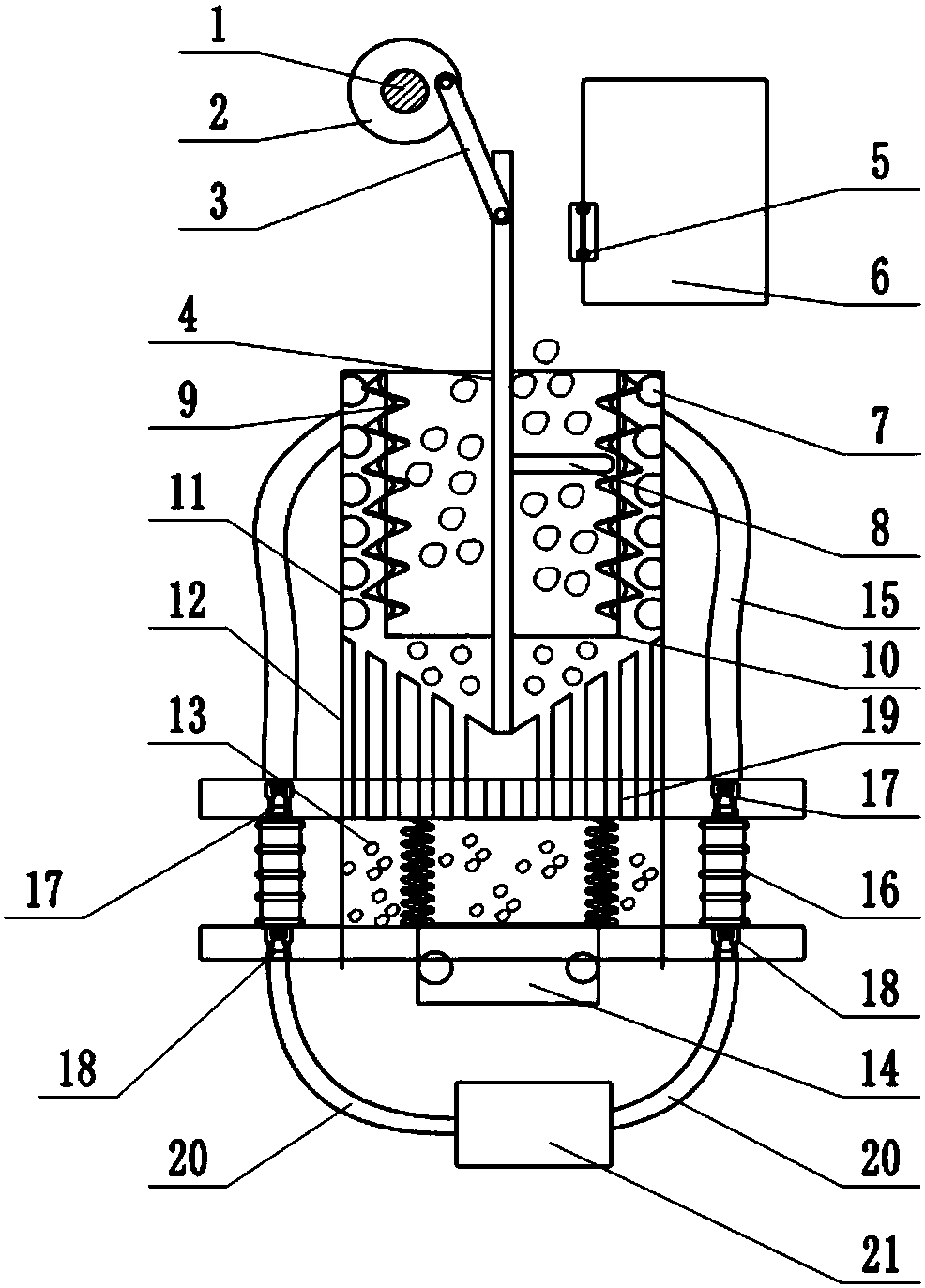
[0023] The difference between this embodiment and Embodiment 1 is that: figure 2 As shown, the upper end of the third-stage crushing part is provided with a rigid sieve plate that is opposite to the loophole of the leakage screen 12 and is slidably connected with the outer wall 11. The two ends of the rigid sieve plate protrude from the outer wall 11 of the crushing box. One end of the spring is connected to the lower end of the third-stage crushing part. Both ends of the rigid sieve plate are provided with bellows 16 connected to the lower end of the third-stage crushing part. The upper end of the bellows 16 is provided with a negative pressure check valve 17 facing the lower end of the third-stage crushing part. The negative pressure one-way valve 17 is connected with the first pipeline 15 extending into the outer wall 11, the lower end of the bellows 16 is provided with a positive pressure one-way valve 18 towards the outside of the lower end of the third-stage crushing par...


PUM


Abstract

The invention belongs to the technical field of mechanical equipment and particularly discloses a crushing machine. The crushing machine comprises a driving unit. A slide bar is hinged to the drivingunit. The slide bar is connected with a threaded rod. A feed box is arranged on one side of the driving unit. One side of the feed box is provided with a one-way feed door. A crushing unit is arrangedbelow the feed box. The crushing unit comprises a first-stage crushing part, a second-stage crushing part and a third-stage crushing part. The first-stage crushing part comprises a crushing box. Thecrushing box comprises an outer wall and an inner wall. The inner wall is of a hollow structure. The lower end of the inner wall is provided with a port. A cavity is formed between the outer wall andthe inner wall. The outer wall is provided with a plurality of protrusions distributed in a staggered mode. The inner wall is provided with feed ports. The inner wall is further provided with a spiral. The second-stage crushing part comprises a leakage net. The third-stage crushing part is arranged under the leakage net. The upper end of the third-stage crushing part is provided with a notch. Oneside of the third-stage crushing part is provided with a one-way discharge door. By adopting the crushing machine, the problems of the poor crushing effect, high cost and inconvenient operation are solved.

Description

technical field [0001] The invention belongs to the technical field of mechanical equipment, and in particular relates to a crusher. Background technique [0002] Crushing is a process in which an external force is applied to the crushed material to overcome the cohesive force between the molecules of the material and split the large material into several small pieces. Crushing operations are divided into mechanical energy crushing and non-mechanical energy crushing such as electrical energy and thermal energy according to the energy consumed. In industry, mechanical force is mainly used for crushing, and the methods are as follows: crushing, chopping, breaking, grinding, impact crushing, etc. [0003] Traditionally, the crushing method used for material crushing is relatively simple, and the material cannot be completely crushed by only primary crushing or grinding, and the crushing effect is poor. At present, there are also multi-stage crushing operations for materials a...

Claims


Application Information

Patent Timeline
IPC IPC(8): B02C19/22B02C1/00B02C23/16B02C23/00B07B1/50
CPCB02C1/00B02C19/22B02C23/00B02C23/16B02C2023/165B07B1/50
Inventor 杨会
Owner 涌纬集团股份有限公司
Why Eureka
Try Eureka