Cloth perforating device

A punching device and cloth technology, applied in the field of cloth processing, can solve problems such as complicated operation, and achieve the effect of increasing the strength of pulling resistance

Active Publication Date: 2018-07-20
NINGBO WENZE TEXTILE CO LTD
View PDF6 Cites 2 Cited by
  • Summary
  • Abstract
  • Description
  • Claims
  • Application Information

AI Technical Summary

Problems solved by technology

In the process of fabric making curtains, it is necessary to punch some small holes on the fabric, so that the hanging loops of the curtain can be passed through the small holes, but the existing fabric punching device cannot automatically move the fabric, and needs to manually move the fabric, so that The fabric punching device punches small holes in different positions of the fabric, so the operation is more complicated when punching holes

Method used


Image

  • Cloth perforating device
  • Cloth perforating device
  • Cloth perforating device

Examples


Embodiment Construction

[0015] The following is further described in detail through specific implementation methods:

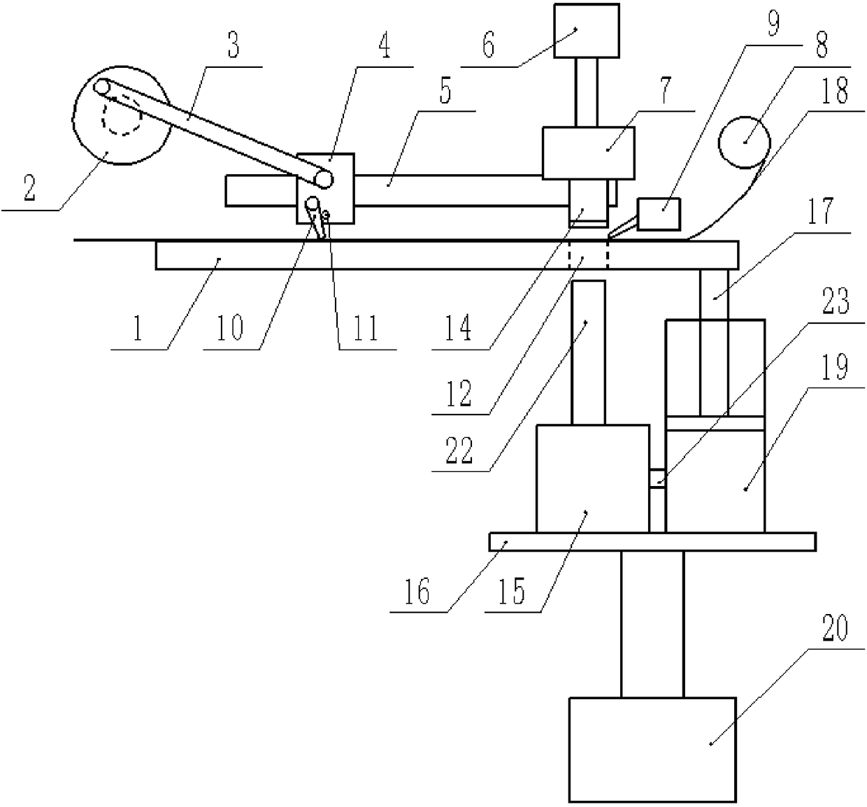
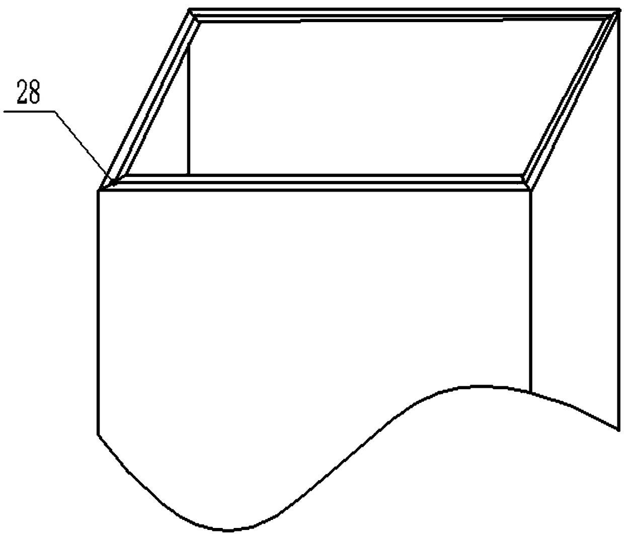
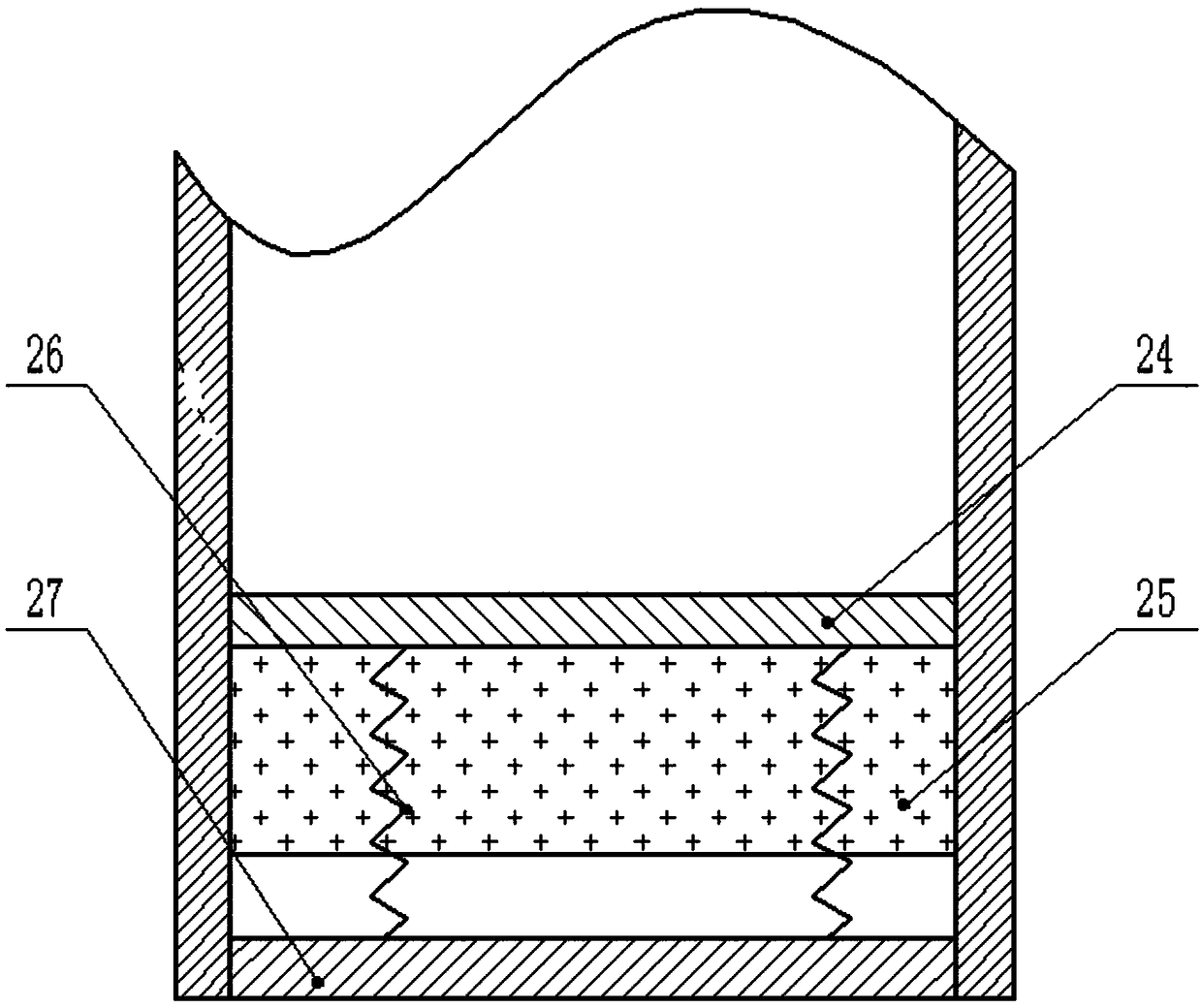
[0016] The reference signs in the drawings of the description include: processing table 1, turntable 2, connecting rod 3, slider 4, slide rail 5, first cylinder 6, water tank 7, cloth roller 8, spray gun 9, claw 10, limit Column 11, through hole 12, water pipe 14, collection box 15, connecting plate 16, piston rod 17, cloth 18, piston cavity 19, second cylinder 20, suction pipe 22, ventilation pipe 23, fixing plate 24, sponge 25, spring 26 , slide plate 27, cutter 28.

[0017] The embodiment is basically as attached Figure 1-Figure 3 Shown: a cloth punching device, including a cloth roller 8 and a processing table 1, the cloth roller 8 is located on the upper right of the processing table 1, cloth 18 is wound on the cloth roller 8, and the processing table 1 is provided with a vertically arranged through-hole Hole 12, the top of processing table 1 is provided with water tank 7 and...


PUM


Abstract

The invention relates to a cloth perforating device which comprises a cloth roll and a machining table. A vertically formed through hole is formed in the machining table, and a water tank and a spraying gun are arranged above the machining table. The water tank is connected with a first driving mechanism and a water pipe aligned to the through hole, and a pressure valve is arranged at the end, away from the water tank, of the water pipe. A spray head pointing to the through hole is arranged on the spraying gun. A reciprocating mechanism and a sliding rail are further arranged above the machining table, and the sliding rail is in sliding connection with a sliding block connected with the reciprocating mechanism. The sliding block is rotationally connected with a claw, a smooth face is arranged on the side, close to the through hole, of the claw, and the sliding block is fixedly connected with a limiting column for enabling the claw to swing in one direction. A second driving mechanism is arranged below the machining table and connected with a collecting box and a piston cavity, and the collecting box is connected with an iron suction pipe. The suction pipe is aligned to the throughhole, a tool is arranged, and the machining table is fixedly connected with a piston rod. A rubber plug is arranged on the piston rod, and the piston cavity communicates with the collecting box. According to the scheme, automation movement of cloth is achieved.

Description

technical field [0001] The invention relates to the technical field of cloth processing, in particular to a cloth punching device. Background technique [0002] Cloth is a commonly used material in decorative materials. Fabrics include chemical fiber carpets, non-woven wall coverings, linen cloth, nylon cloth, colored tape, flannel and other fabrics. In the process of fabric making curtains, it is necessary to punch some small holes on the fabric, so that the hanging loops of the curtain can be passed through the small holes, but the existing fabric punching device cannot automatically move the fabric, and needs to manually move the fabric, so that The cloth punching device punches small holes in different positions of the cloth, so the operation is more complicated when punching. Contents of the invention [0003] The object of the present invention is to provide a cloth punching device to realize the automatic movement of the cloth without manually moving the cloth dur...

Claims


Application Information

Patent Timeline
Patent Type & Authority Applications(China)
IPC IPC(8): B26F1/00B26D7/20B26D7/18B26D7/32
CPCB26D7/18B26D7/20B26D7/32B26F1/00
Inventor 孙文清
Owner NINGBO WENZE TEXTILE CO LTD
Why Eureka
Try Eureka