Tilting-pad sliding bearing

A sliding bearing and bearing housing technology, applied in the directions of bearings, bearing components, shafts and bearings, can solve the problems of increasing the bearing cross stiffness damping coefficient, complicated installation of tilting pad bearings, high fulcrum contact stress and fatigue, etc. Eliminate wear, increase stiffness and damping, and improve vibration

Active Publication Date: 2018-07-20
GUANGZHOU MARITIME INST
View PDF6 Cites 5 Cited by
  • Summary
  • Abstract
  • Description
  • Claims
  • Application Information

AI Technical Summary

Problems solved by technology

[0004] With the rapid development of industry, the speed of rotating machinery continues to increase, and the performance requirements continue to improve; the traditional mechanical fulcrums often used in existing tilting pad bearings make the installation of tilting pad bearings complicated and have high fulcrum contact stress and contact stress in working conditions. Fatigue will increase the damping coefficient of bearing cross stiffness and bring about unstable factors

Method used


Image

  • Tilting-pad sliding bearing
  • Tilting-pad sliding bearing
  • Tilting-pad sliding bearing

Examples


Embodiment 1

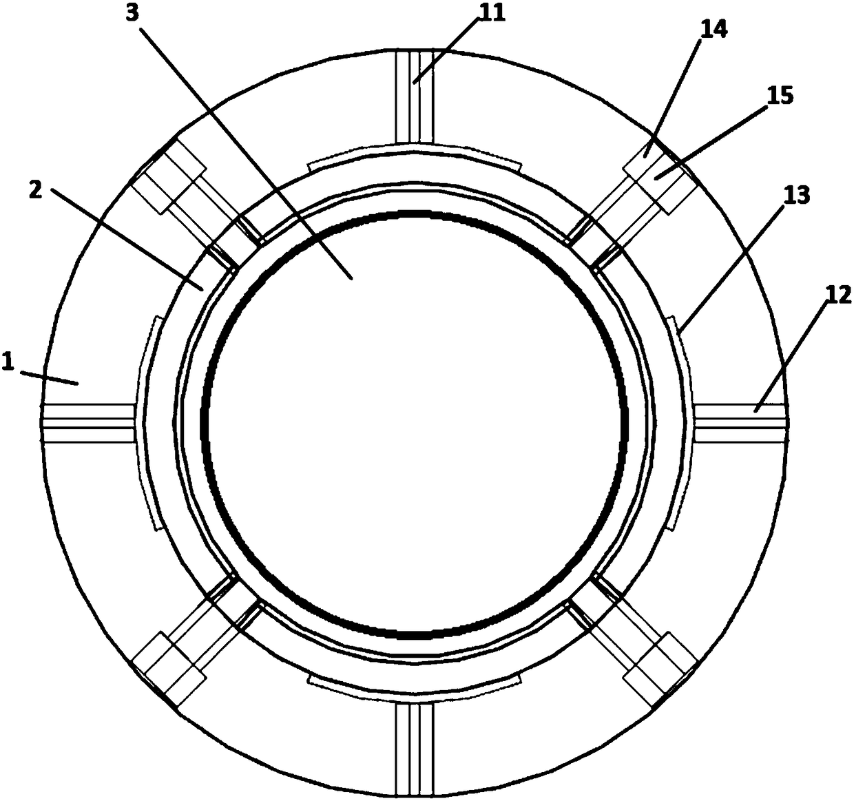
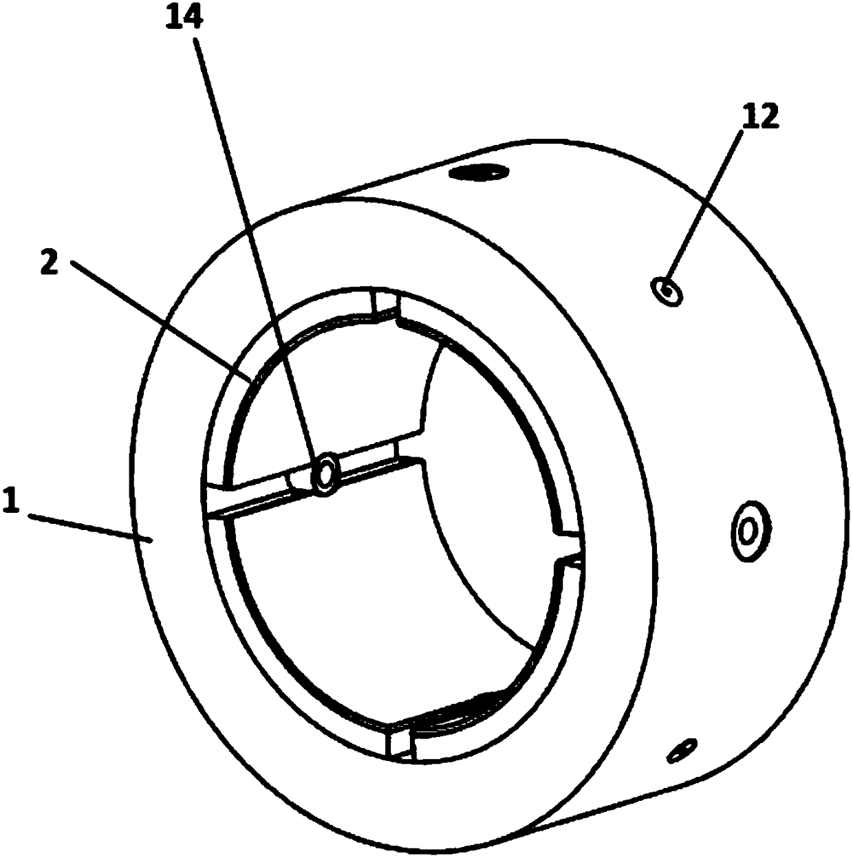
[0026] Such as figure 1 as shown, figure 1 It is a three-dimensional structure view of the tilting pad sliding bearing; the tilting pad sliding bearing includes a bearing housing 1, and the bearing housing 1 is arranged as a hollow cylindrical structure, and on the inner surface of the bearing housing 1 A number of pads 2 are arranged, and the pads 2 are evenly distributed in a ring shape around the central axis of the bearing housing 1 ; the rotor 3 is arranged in the ring structure formed by the pads 2 . Both sides of the bearing housing 1 are connected to the bearing end cover by bolts.

[0027] The bearing housing 1 can be configured as an integral structure or a split structure. The tilting pad sliding bearings can be divided into three-watt, four-watt, five-watt and other multi-watt tilting pad bearings according to the number of the pads 2

[0028] The bearing housing 1 is provided with several throttle holes 11 in the radial direction. Preferably, the throttle holes...

Embodiment 2

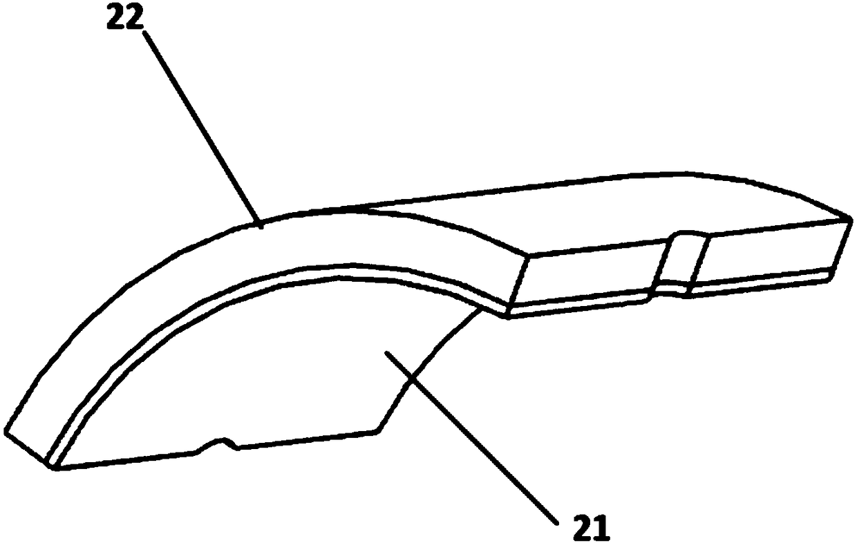
[0032] In this embodiment, the tilting pad sliding bearing includes four pads 2; the pads 2 are arc-shaped, such as image 3 as shown, image 3 It is a structural view of the tile; the tile 2 includes a friction-reducing layer 21 and a tile back base 22, and the friction-reducing layer 21 is fixedly arranged on the end surface of the tile back base 22 opposite to the rotor 3; And in order to better form an inner hydrodynamic lubricating film and an outer hydrostatic film on the two arc-shaped end surfaces of the tile 2, the tile 2 has a certain preload coefficient.

[0033] The preload coefficient m reflects the degree of convergence of the oil wedge on the inner surface of each of the pads 2; specifically, the greater the preload coefficient m, the greater the degree of convergence of the oil wedge on the inner surface of the tile 2, which can force The lubricating medium enters the convergent gap to increase the oil wedge force acting on the rotor journal, thereby tightly c...

Embodiment 3

[0040] Embodiment 3 is further improved on the basis of Embodiment 1. In this embodiment, the bearing housing 1 is provided with a throttle 12 radially, and the throttle 12 is detachably fixed on the bearing housing 1; the throttle hole 11 is arranged on the throttle 12 Above; the cross-sectional size of the orifice 11 can be freely set by replacing the restrictor 12, so as to adjust the flow rate of the lubricating medium through the orifice 11 and other parameters. Such as Figure 4 as shown, Figure 4 It is a structural view of the bearing housing; the tilting pad sliding bearing also includes a static pressure shallow chamber 13, and the static pressure shallow chamber 13 is arranged on the bearing housing 1 or / and the pad 2, The static pressure shallow chamber 13 is set at the inner end of the bearing housing 1 corresponding to the throttle hole 11, that is, enters the gap between the bearing housing 1 and the pad 2 through the throttle hole 11 The internal lubricating...


PUM


Abstract

The invention discloses a tilting-pad sliding bearing which comprises a plurality of broken tiles, a bearing shell and bearing end covers. The bearing shell is arranged to be of a hollow cylinder structure; the broken tiles are annularly and uniformly distributed on an inner surface of the bearing shell around a central axis of the bearing shell; a rotor is arranged in an annular structure formedby the broken tiles; two sides of the bearing shell are connected with the bearing end covers; a plurality of throttling holes are formed in a radial direction of the bearing shell and are formed in positions, corresponding to the centers of the broken tiles, of the bearing shell; and a high-pressure lubricating medium enters gaps between the bearing shell and the broken tiles through the throttling holes so as to form hydrostatic pressure supporting points for supporting the broken tiles. According to the tilting-pad sliding bearing provided by the invention, the hydrostatic pressure supporting points are adopted to replace mechanical supporting points in the prior art, so that the wear of the mechanical supporting points of the broken tiles is eliminated, and the vibration of a bearing-rotor system is improved.

Description

technical field [0001] The invention relates to the technical field of bearings, in particular to a tilting pad sliding bearing. Background technique [0002] During the operation of rotating mechanical equipment, certain vibrations are often generated, which affects the stable state of each component of the system, reduces the working efficiency of the machinery and equipment, increases the friction and wear between matching parts, and affects the quality of the product. Severe vibration will produce strong vibration noise, damage machine parts, cause machine failure, and even cause accidents. The tilting pad bearing is used as the support of the rotor system, and its lubricating oil film not only produces the bearing capacity of the oil film, but also reduces friction and vibration. The tilting pad bearing has a certain self-aligning ability through the swing of the pad, and the support rotation accuracy is high. And it has good stability and vibration resistance, so it i...

Claims


Application Information

Patent Timeline
Patent Type & Authority Applications(China)
IPC IPC(8): F16C32/06F16C33/04F16C37/00
CPCF16C32/06F16C33/04F16C37/00
Inventor 杨期江李伟光李锻能汤雅连
Owner GUANGZHOU MARITIME INST
Why Eureka
Try Eureka