
Magnetic powder brake water cooling structure

A magnetic powder brake and water cooling technology, which is applied in the direction of brake types, slack regulators, mechanical equipment, etc., can solve the problems of large impact on the production process, high cost, looseness at the water connection, etc., and achieve good sealing and leak-proof effect, structure Reasonable and stable, easy to disassemble and maintain

Active Publication Date: 2018-07-20
JIANGSU LANLING ELECTROMECHANICAL TECH CO LTD
View PDF5 Cites 0 Cited by
  • Summary
  • Abstract
  • Description
  • Claims
  • Application Information

AI Technical Summary

Problems solved by technology

Since the cooling shaft is always in a state of friction during the working process of the magnetic powder brake, it is easy to wear after a long time of work, so that the magnetic powder brake leaks and is scrapped
In addition, in the prior art, the cooling shaft and the rotor are combined and welded together. Once the cooling shaft is scrapped, the components including the rotor assembly need to be replaced, which is expensive, requires a large replacement action, takes a long time, and has a relatively large impact on the production process. Big
After a long time of use, the water connection port on the water-cooled magnetic powder brake sometimes becomes loose and causes water leakage.

Method used


Image

  • Magnetic powder brake water cooling structure
  • Magnetic powder brake water cooling structure
  • Magnetic powder brake water cooling structure

Examples


Embodiment Construction

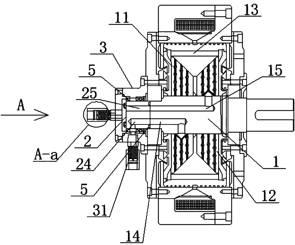
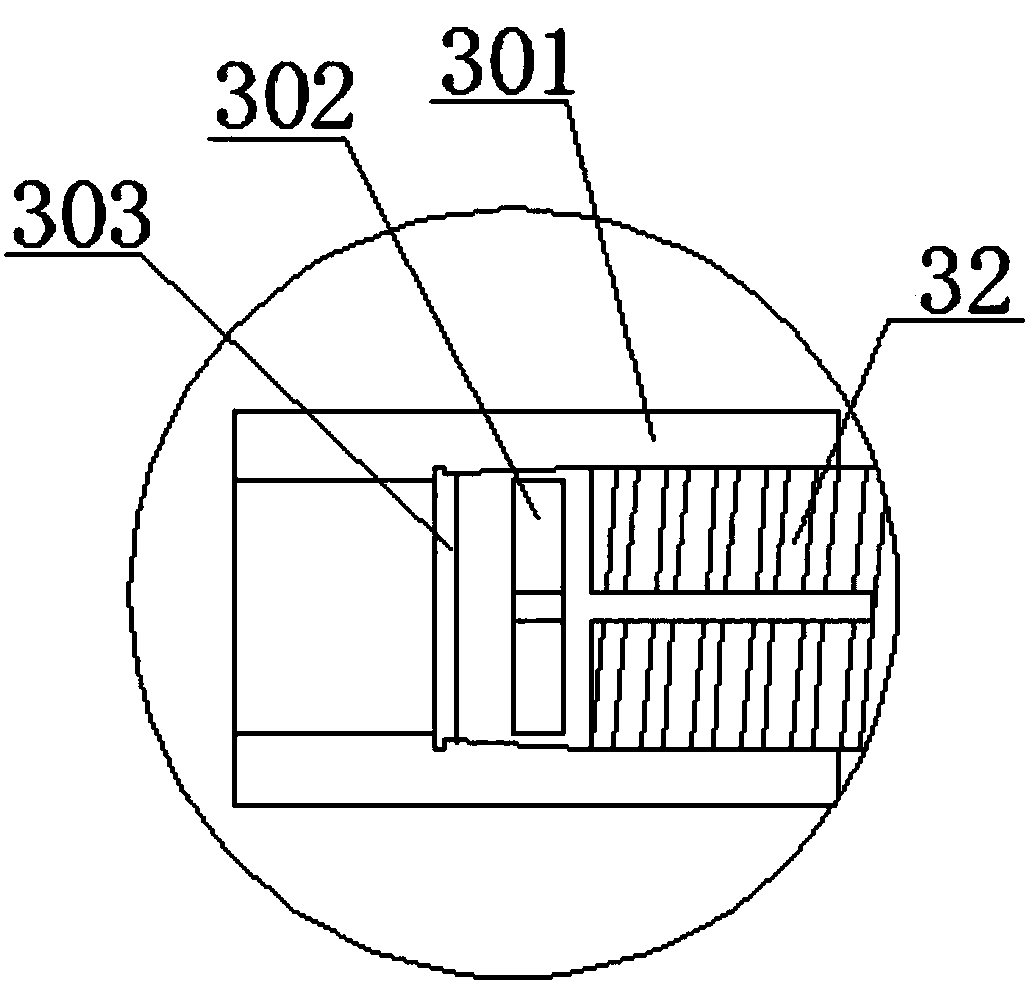
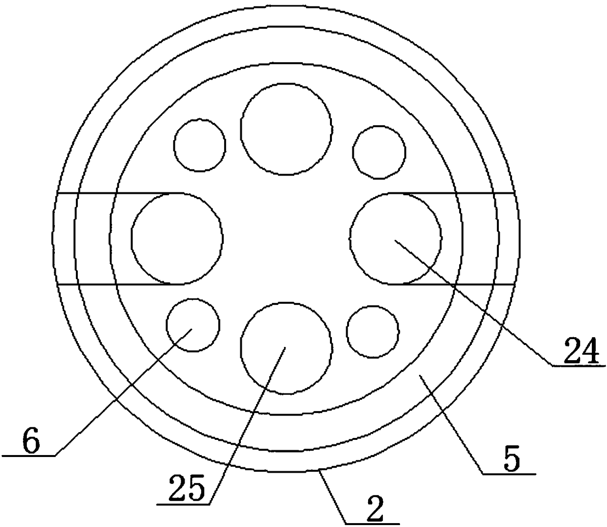
[0021] Such as Figure 1 to Figure 4 As shown, a magnetic powder brake water cooling structure includes a rotor assembly 1 that can rotate around an axis and a cooling shaft 2 coaxially and detachably fixed on the rotor assembly 1 . In the present invention, the cooling shaft 2 refers to a piece of workpiece that is detachably connected to the rotor assembly and has friction with the water seal cover 3 . In the prior art, the integrated casting of the rotor assembly and the output shaft is difficult and costly. To ensure power transmission, the rotor assembly and the output shaft are generally forged separately and then welded together. This is obviously different from the design of the present invention which is provided with the cooling shaft 2 and detachably connected to the rotor assembly, and the cooling shaft 2 is generally also a part of the output shaft and cannot be confused with the output shaft.

[0022] The above-mentioned water cooling structure for the magnetic ...


PUM


Abstract

The invention provides a magnetic powder brake water cooling structure. The magnetic powder brake water cooling structure comprises a rotor assembly capable of rotating around the axis, a cooling shaft coaxially and detachably fixed to the rotor assembly, a first cavity and a second cavity, wherein the first cavity and the second cavity are formed in the rotor assembly; the first cavity and the second cavity are internally provided with auxiliary parts; the auxiliary parts include the first auxiliary part and the second auxiliary part; the first auxiliary part comprises hollow columns and hollow spheres, the hollow spheres are arranged on the hollow columns; the second auxiliary part comprises a hollow frame, and hollow spheres are arranged on the hollow frame; the rotor assembly is axially provided with main channels; the main channels communicate with the first cavity and the second cavity; the cooling shaft is axially provided with four auxiliary channels; when the cooling shaft isconnected with the rotor assembly, the main channels of the rotor assembly communicate with the corresponding auxiliary channels of the cooling shaft. The magnetic powder brake water cooling structureprovided by the invention has the advantages of being reasonable and stable in structure, convenient to dismantle and maintain and good in sealing and leak-proof effect and effectively guaranteeing the service life.

Description

technical field [0001] The invention relates to a cooling structure in a magnetic powder brake, in particular to a water cooling structure for a magnetic powder brake. Background technique [0002] Magnetic powder brake is a multi-purpose, high-performance automatic control element, widely used in locomotive start, simulated load, wire and cable, metallurgy, tablet press machine and other winding and tension control, the magnetic powder in the magnetic powder brake produces magnetic linkage under the action of the magnetic force , so that the output shaft and the input shaft rotate as a rigid body, and slip occurs during operation, and the slip causes part of the energy to be converted into heat. Generally, the temperature must be controlled below 75°C during operation. When the temperature exceeds this temperature, it will affect the magnetic powder. service life of the brake. [0003] Water-cooled magnetic powder brakes have gradually become the mainstream of high-end mag...

Claims


Application Information

Patent Timeline
Patent Type & Authority Applications(China)
IPC IPC(8): F16D63/00F16D65/78
CPCF16D63/002F16D65/78
Inventor 薛永贵顾耸智顾耸明
Owner JIANGSU LANLING ELECTROMECHANICAL TECH CO LTD
Learn More