
Solar lighting device

A lighting device and solar energy technology, applied in the field of lighting, can solve the problems of low solar energy conversion efficiency, cumbersome installation and disassembly steps of lighting lamps, etc., and achieve the effect of convenient operation and simple structure

Inactive Publication Date: 2018-07-20
NINGBO CITY DAZHIFENG IND PROD DESIGN CO LTD
View PDF0 Cites 0 Cited by
  • Summary
  • Abstract
  • Description
  • Claims
  • Application Information

AI Technical Summary

Problems solved by technology

[0002] Solar lighting uses solar energy as energy, and realizes photoelectric conversion through solar cells. During the day, batteries are used to save and store electric energy, and at night, the controller supplies power to the electric light source to achieve the required functional lighting. The current solar photovoltaic panels are generally directly fixed. On the installation frame, its solar energy conversion efficiency is low, and the installation and removal steps of the lighting lamp are cumbersome

Method used


Image

  • Solar lighting device
  • Solar lighting device
  • Solar lighting device

Examples


Embodiment Construction

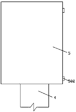
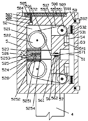
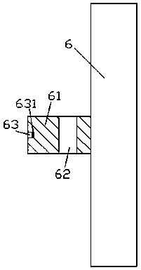
[0012] Combine below Figure 1-Figure 3 The present invention will be described in detail.

[0013] refer to Figure 1-Figure 3 , according to an embodiment of the present invention, a solar lighting device includes a fixing frame body 5 fixedly installed on the support frame 4 and a lighting lamp body 6 used to cooperate with the fixing frame body 5 , the device An accommodating cavity 504 is arranged in the top end surface of the fixed frame body 5, and a fixing plate 508 is arranged in the accommodating cavity 504, and the right end surface of the fixing plate 508 is hingedly connected with the right side wall of the accommodating cavity 504 through a hinge shaft 509 A photovoltaic panel 507 is fixedly installed in the receiving cavity 504 on the top end surface of the fixing plate 508, and a dovetail groove 505 is arranged on the left side of the lower end surface of the fixing plate 508, and the dovetail groove 505 A dovetail block 506 is installed in a sliding fit, and...


PUM


Abstract

The invention relates to a solar lighting device. The solar lighting device comprises an assembled rack body fixedly mounted on a supporting rack and a lighting lamp body matched with and connected tothe assembled rack body, wherein an accommodating cavity is formed in the end surface of the top of the assembled rack body; an assembling plate is arranged in the accommodating cavity; the right endsurface of the assembling late is matched with and connected to the right side wall of the accommodating cavity through a hinged shaft in a hinged manner; a photovoltaic panel is fixedly mounted in the accommodating cavity in the end surface of the top of the assembling plate; dovetail grooves are formed in the lower end surface, close to the left side, of the assembling plate in an extending manner left and right; dovetail blocks are slidably mounted in the dovetail grooves in a matched manner; a spiral columns is hinged, matched and mounted on the end surface of the bottom of each dovetailblock; a spiral sleeve is mounted in a screw-thread fit manner on the spiral column; the spiral sleeve is rotatably arranged in the bottom wall of the accommodating cavity in a matched manner; and a first motor is mounted in a power match manner at the extended tail end of the bottom of the spiral sleeve.

Description

technical field [0001] The invention relates to the technical field of lighting, in particular to a solar lighting device. Background technique [0002] Solar lighting uses solar energy as energy, and realizes photoelectric conversion through solar cells. During the day, batteries are used to save and store electric energy, and at night, the controller supplies power to the electric light source to achieve the required functional lighting. The current solar photovoltaic panels are generally directly fixed. On the installation frame, its solar energy conversion efficiency is low, and the installation and disassembly steps of the lighting lamp are loaded down with trivial details. Contents of the invention [0003] The object of the present invention is to provide a solar lighting device for overcoming the above-mentioned defects in the prior art. [0004] A solar lighting device according to the present invention, comprising a fixing frame body fixedly installed on a suppo...

Claims


Application Information

Patent Timeline
Patent Type & Authority Applications(China)
IPC IPC(8): F21S9/03F21V23/00H02S20/32
CPCF21S9/03F21V23/02H02S20/32Y02E10/50
Inventor 楼华
Owner NINGBO CITY DAZHIFENG IND PROD DESIGN CO LTD
Learn More