Modular multifunctional test fixture in free space method
A technology of free space and test fixtures, applied in the direction of measuring devices, measuring electrical variables, measuring device casings, etc., can solve problems such as lack of suitable fixtures, and achieve the effect of preventing reflection interference
- Summary
- Abstract
- Description
- Claims
- Application Information
AI Technical Summary
Problems solved by technology
Method used
Image
Examples
Embodiment 1
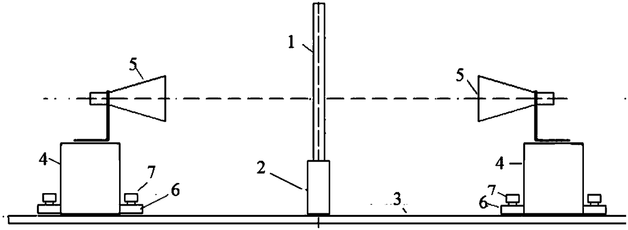
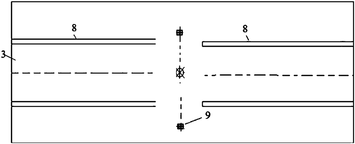
[0035] This embodiment provides a modular multifunctional free space method test fixture, which is specially designed for the transmission method to test the electromagnetic parameters of powdery or granular materials; Figure 1-2 As shown, the included fixture includes:
[0036] 1) The antenna base plate 3 is provided with grooves parallel to each other on the antenna base plate 3; specifically: on both sides of the sample box support 2, two parallel grooves 8 are respectively set, and marked on the grooves Scale; on both sides of the antenna bottom plate, there are bracket holes 9 for inserting the sample box bracket 2;
[0037] 2) Antenna base 4; the antenna base includes a first antenna base and a second antenna base which are respectively arranged on both sides of the antenna base plate; in the present embodiment, two test antennas 5 are respectively fixed on the first antenna base base and the upper part of the second antenna base. A slide rail corresponding to the gro...
Embodiment 2
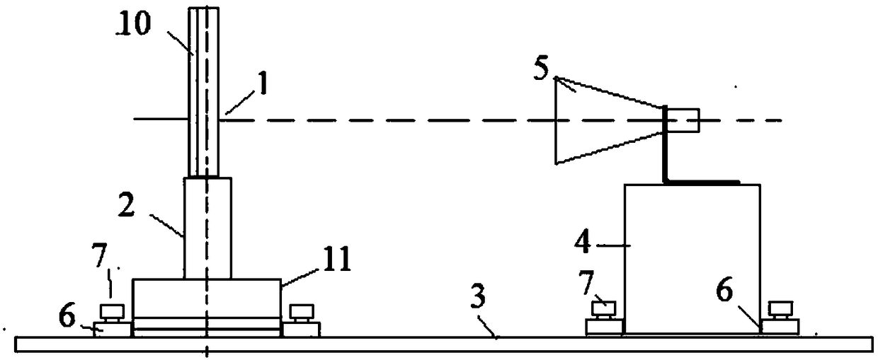
[0046] This embodiment provides a modular multifunctional free space method test fixture, which is specially designed for the reflection method to test the electromagnetic parameters of powdery or granular materials; image 3 As shown, the fixture includes: antenna base plate 3, antenna base 4, sample box support 2, sample box 1 fixed on the sample box support, and a test antenna 5 fixedly arranged on the antenna base 4;
[0047] The test fixture also includes a calibration base 11; the antenna base 4 is fixedly arranged on one end of the antenna base; the calibration base 11 is arranged on the other end of the antenna base; the sample box support 2 It is arranged on the calibration base 11; the calibration base is designed to meet the requirement that the antenna position cannot be moved during reflection method calibration. Both sides of the calibration base 11 also respectively have a support hole for inserting the sample box support 2 .
[0048] A groove is provided on th...
Embodiment 3
[0059] This embodiment is basically the same as Embodiment 1, the only difference is that, as Figure 5 Said, the fixture also includes a vertical base, when the powdery or granular sample to be measured is not suitable for vertical placement, the antenna bottom plate is vertically inserted into the vertical base, so as to realize the conversion of the sample box from vertical placement to horizontal placement . The clamps provided in Embodiments 1 and 2 are suitable for the situation where the antenna 5 is placed horizontally and the sample box 1 is placed vertically. This placement is convenient for adjusting the distance between the antenna and the sample and is easy to operate. However, sometimes powdery or granular samples are not suitable for vertical placement. For this reason, a special vertical base 12 is designed in this embodiment. Only the antenna base plate is inserted into the vertical base 12, and it is conveniently converted into a sample. Box 1 is placed hori...
PUM
 Abstract
Description
Claims
Application Information
 - R&D
- Intellectual Property
- Life Sciences
- Materials
- Tech Scout
- Unparalleled Data Quality
- Higher Quality Content
- 60% Fewer Hallucinations
Browse by: Latest US Patents, China's latest patents, Technical Efficacy Thesaurus, Application Domain, Technology Topic, Popular Technical Reports.
© 2025 PatSnap. All rights reserved.Legal|Privacy policy|Modern Slavery Act Transparency Statement|Sitemap|About US| Contact US: help@patsnap.com


