Magnetic resonance imaging system eddy current compensation method

A technology of magnetic resonance imaging and compensation method, which is applied in the direction of measuring magnetic variables, measuring devices, instruments, etc., can solve problems such as lowering system performance, large use restrictions, and narrow response frequency band, so as to improve system performance, reduce hardware cost, and operate easy effect

Active Publication Date: 2018-07-20
ALLTECH MEDICAL SYST
View PDF5 Cites 9 Cited by
  • Summary
  • Abstract
  • Description
  • Claims
  • Application Information

AI Technical Summary

Problems solved by technology

[0006] The purpose of the present invention is to provide an eddy current compensation method for magnetic resonance imaging systems, which is used to solve the problems of high hardware cost, reduced system performance, large use restrictions and narrow response frequency bands in the existing eddy current compensation methods

Method used


Image

  • Magnetic resonance imaging system eddy current compensation method
  • Magnetic resonance imaging system eddy current compensation method
  • Magnetic resonance imaging system eddy current compensation method

Examples


Embodiment Construction

[0038] In order to make the object, technical solution and advantages of the present invention clearer, the present invention will be further described in detail below in conjunction with the accompanying drawings.

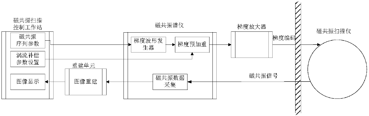
[0039] like Figure 4 , Figure 5 As shown, a magnetic resonance imaging system eddy current compensation method includes the following steps:

[0040] Step a, the magnetic resonance spectrometer generates the waveform of the gradient magnetic field according to the scanning sequence parameters and outputs it to the gradient amplifier to drive the magnetic resonance scanner to work, and the magnetic resonance spectrometer collects magnetic resonance data;

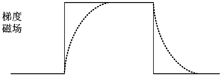
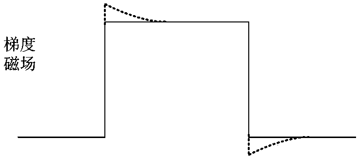
[0041] Step b. Perform gradient trajectory correction according to the ideal gradient waveform and eddy current compensation parameters, that is, calculate the waveform of the gradient magnetic field affected by the eddy current with time, and then obtain the corrected K-space trajectory;

[0042] Step c. The...


PUM


Abstract

The invention discloses a magnetic resonance imaging system eddy current compensation method, and belongs to the technical field of magnetic resonance imaging. The method includes the following steps:a, a magnetic resonance spectrometer generates a waveform of a gradient magnetic field according to scanning sequence parameters and outputs the waveform to a gradient amplifier, drives a magnetic resonance scanner to work, and the magnetic resonance spectrometer collects magnetic resonance data; b, gradient trajectory correction is performed according to scanning sequence parameters and eddy current compensation parameters, i.e., the waveform of the gradient magnetic field which changes with time after being influenced by eddy currents is calculated, thereby obtaining a corrected K space trajectory; and c, gridding reconstruction is performed on the magnetic resonance data collected in Step a according to the corrected K space trajectory obtained in Step b or nonuniform Fourier transformation is utilized to reconstruct a magnetic resonance image. The method provided by the invention performs eddy current compensation based on software, avoids hardware input, and improves imaging quality.

Description

technical field [0001] The invention relates to the technical field of magnetic resonance imaging, in particular to an eddy current compensation method for a magnetic resonance imaging system. Background technique [0002] In the process of magnetic resonance imaging, the gradient magnetic field, the main magnetic field and the radio frequency magnetic field together constitute the three major elements of magnetic resonance imaging. The gradient magnetic field is generated by the gradient coil. The current in the gradient coil switches rapidly with time, which will generate eddy current in the surrounding conductor structure. The eddy current will generate a magnetic field that is constantly changing in space and time, which will distort the gradient field in the imaging area. And then affect the image quality, such as figure 1 As shown, the solid line in the figure is the waveform of the ideal gradient magnetic field, and the dotted line is the waveform affected by the edd...

Claims


Application Information

Patent Timeline
IPC IPC(8): G01R33/565
CPCG01R33/56518
Inventor 罗海王文周朱高杰周翔王超陈梅泞刘霞吴子岳
Owner ALLTECH MEDICAL SYST
Why Eureka
Try Eureka