DMD structure XY multi-shaft movable optical path direct writing exposure machine
An exposure machine and optical path technology, which is applied in the field of DMD structure XY multi-axis movable optical path direct writing exposure machine, can solve the problems of inability to produce super large boards, inaccurate focus and positioning, and air leakage of vacuum suction cups, so as to improve exposure accuracy and Stability of operation, accurate exposure position, and no edge lifting effect
- Summary
- Abstract
- Description
- Claims
- Application Information
AI Technical Summary
Problems solved by technology
Method used
Image

Examples
Embodiment 1
[0073] Example 1: Vacuum chuck
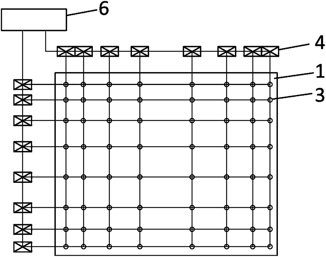
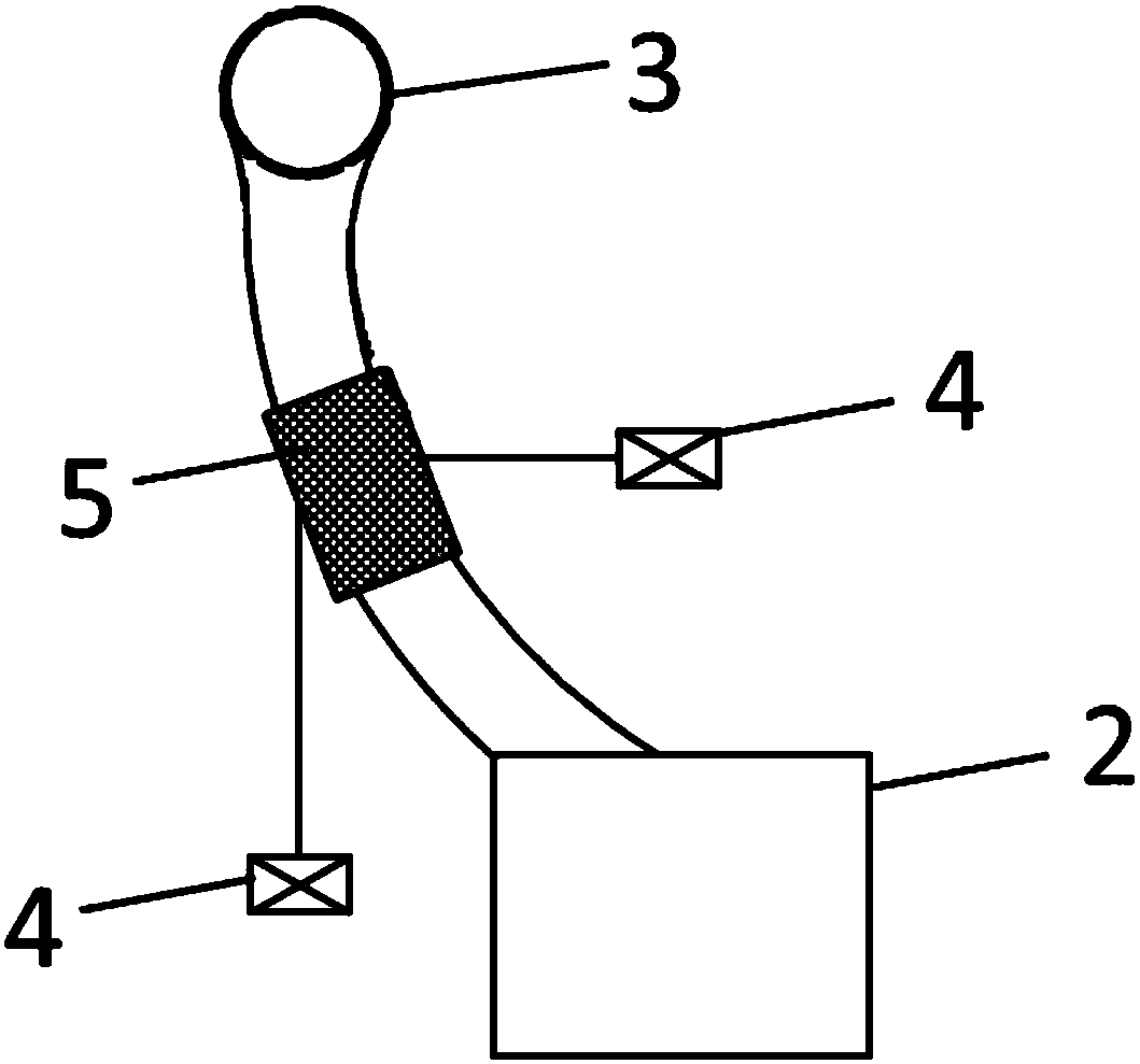
[0074] The vacuum chuck structure of the present invention is as Figure 1-2 shown.
[0075] The vacuum suction cup of the present invention includes a suction cup main body 1 and a vacuum generating device 2; a certain number of air holes 3 are distributed in the form of rows and columns on the suction cup main body 1, each row of air holes 3 corresponds to a relay 4, and each column of air holes 3 also corresponds to one A relay 4; an air hole switch 5 is connected between each air hole 3 and the vacuum generating device 2; the air hole switch 5 is connected to the relay 4 in the row where the air hole 3 is located and the relay 4 in the column where the air hole 3 is located.
[0076] Each relay 4 is connected to the overall control device 6 . The air hole switch 5 is located on the vacuum pipeline connected between the air hole 3 and the vacuum generating device 2 . The air hole switch 5 may be an electromagnetic switch. The air holes 3...
Embodiment 2
[0078] Example 2: Vacuum chuck
[0079] The vacuum chuck of the present embodiment, in embodiment 1 such as Figure 1-2 A modified version of the vacuum cup shown.
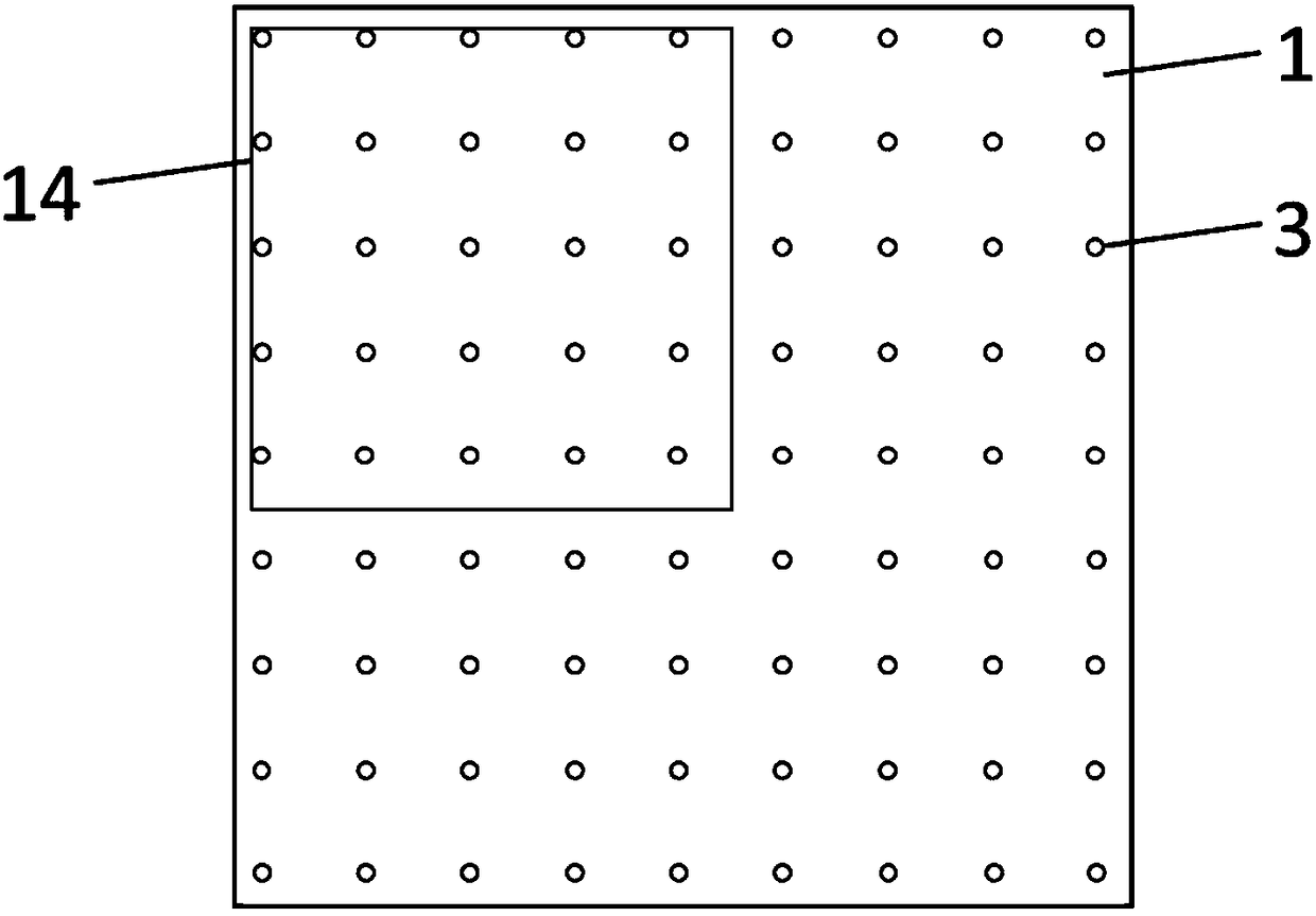
[0080] The air holes 3 on the main body 1 of the suction cup are distributed sparsely in the middle and densely around.
[0081] In traditional vacuum chucks, the air holes are generally evenly distributed. When producing a small PCB, it is possible that after the substrate 14 is placed on the main body of the suction cup, a certain edge of the substrate is located far away from the air holes on both sides (such as image 3 As shown), the edge part will be lifted due to the lack of vacuum suction, which will affect the production. After adopting the distribution form of the present invention, which is sparse in the middle and dense around, such as Figure 4-5 As shown, when a small substrate is placed on the vacuum chuck, choose to place the substrate close to the edge of the suction cup body. Move to the near...
Embodiment 3
[0085] Example 3: DMD structure XY dual-axis movable optical path direct writing exposure machine
[0086] Take the DMD structure XY dual-axis movable optical path direct writing exposure machine with two moving components as an example to illustrate.
[0087] Such as Image 6 Shown is a DMD structure XY dual-axis movable optical path direct writing exposure machine containing the vacuum chuck of the present invention.
[0088] The DMD structure XY dual-axis movable optical path direct writing exposure machine includes a support structure 7, a DMD structure 8, a DMD structure stepping axis 9, a plurality of moving components, and a vacuum chuck 10; each moving component includes a stepping X axis 11 , a scanning Y-axis 12 and a lifting Z-axis 13; the vacuum chuck 10 is located above the moving assembly.
[0089]The DMD structure 8 is installed on the DMD structure stepping shaft 9 and can move along the guide rail with the slider of the DMD structure stepping shaft 9 . The ...
PUM
| Property | Measurement | Unit |
|---|---|---|
| area | aaaaa | aaaaa |
Abstract
Description
Claims
Application Information
 - R&D
- Intellectual Property
- Life Sciences
- Materials
- Tech Scout
- Unparalleled Data Quality
- Higher Quality Content
- 60% Fewer Hallucinations
Browse by: Latest US Patents, China's latest patents, Technical Efficacy Thesaurus, Application Domain, Technology Topic, Popular Technical Reports.
© 2025 PatSnap. All rights reserved.Legal|Privacy policy|Modern Slavery Act Transparency Statement|Sitemap|About US| Contact US: help@patsnap.com