Cavity-based filtering balun

A cavity and cavity resonator technology, applied in waveguide-type devices, connecting devices, electrical components, etc., can solve the problems of large insertion loss, low quality factor of resonators, filter balun limitation, etc., and achieve a good passband. Selectivity, high output signal amplitude balance and phase inversion characteristics, effect of reducing circuit size

Active Publication Date: 2018-07-20
广州瀚信通信科技股份有限公司
View PDF6 Cites 4 Cited by
  • Summary
  • Abstract
  • Description
  • Claims
  • Application Information

AI Technical Summary

Problems solved by technology

[0004] However, there are defects such as the low quality factor of the resonator and the large insertion loss in the appeal technology, which limits the design of the filter balun in many practical applications.

Method used


Image

  • Cavity-based filtering balun
  • Cavity-based filtering balun
  • Cavity-based filtering balun

Examples


Embodiment Construction

[0025] The accompanying drawings are for illustrative purposes only, and should not be construed as limitations on this patent; in order to better illustrate this embodiment, certain components in the accompanying drawings will be omitted, enlarged or reduced, and do not represent the size of the actual product; for those skilled in the art It is understandable that some well-known structures and descriptions thereof may be omitted in the drawings. The positional relationship described in the drawings is for illustrative purposes only, and should not be construed as a limitation on this patent.

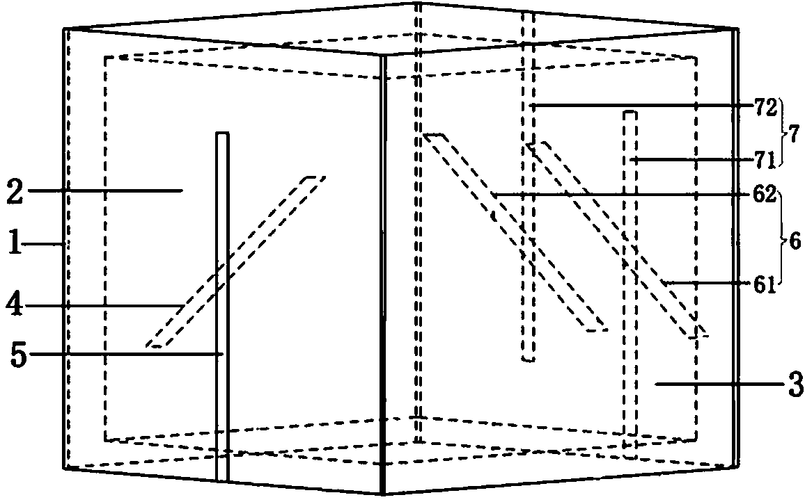
[0026] Such as Figure 1 to Figure 6 As shown, a filter balun based on a cavity, which includes a cavity resonator 1, and the outer sides of the opposite sides of the cavity resonator 1 are respectively provided with an input terminal PCB board 2 and an output terminal PCB board 3 , the input terminal PCB board 2 is provided with an input terminal slot line 4 on the side close to the...


PUM


Abstract

Provided in the invention is a cavity-based filtering balun which comprises a cavity resonator. An input terminal PCB board and an output terminal PCB board are arranged at the two opposite sides of the cavity resonator; an input terminal slot line is arranged at one side, approaching the side of the cavity resonator, of the input terminal PCB board; and an input terminal microstrip line is arranged at the other side. A first slot hole that corresponds to the input terminal slot line completely is arranged at the position corresponding to the input terminal slot line on the side wall of the input terminal PCB board at the cavity resonator; an output terminal slot line is arranged at one side, approaching the side of the cavity resonator, of the output terminal PCB board and an output microstrip line is arranged at the other end; and a second slot hole corresponding to the output terminal slot line completely is arranged at the position corresponding to the output terminal slot line, onthe side wall of the output terminal PCB board at the cavity resonator. According to the invention, the filtering balun body is a cavity resonator, so that the quality factor is improved and the insertion losses are reduced. With the two resonance modes in the cavity resonator, the bipolar transmission band requirement is realized in the single cavity structure; and the circuit dimension is reduced.

Description

technical field [0001] The present invention relates to the technical field of filter balun circuits, and more particularly, to a cavity-based filter balun. Background technique [0002] With the continuous upgrading of modern communication systems and the rapid development of wireless communication technology, more stringent requirements have been placed on RF front-end circuit components. Indicators such as miniaturization and low loss have become important parameters for evaluating the quality of components today. Among them, the fusion design of the circuit can not only integrate the functions of multiple devices into a single circuit, reduce the size of the circuit, but also avoid the loss caused by cascading devices. [0003] Both filters and baluns play an important role in the RF domain. In the past scientific research, the fusion design of filters and baluns has been widely studied, and the design of reducing the size of the entire circuit has been widely used. Th...

Claims


Application Information

Patent Timeline
Patent Type & Authority Applications(China)
IPC IPC(8): H01P1/207H01P5/10
CPCH01P1/207H01P5/10
Inventor 萧振涛
Owner 广州瀚信通信科技股份有限公司
Why Eureka
Try Eureka