Welding equipment for improving efficiency

A technology of welding equipment and efficiency, which is applied in the field of welding equipment to improve efficiency, can solve the problems of insufficient protection measures for materials, easy oxidation of welding materials, difficulty in height adjustment, etc., to achieve improved welding efficiency, convenient use, and high degree of automation Effect

Inactive Publication Date: 2018-07-24
钟丽菊
View PDF0 Cites 7 Cited by
  • Summary
  • Abstract
  • Description
  • Claims
  • Application Information

AI Technical Summary

Problems solved by technology

[0002] The welding device is a device that uses the high-temperature arc generated when the positive and negative poles are short-circuited in an instant to melt the solder on the electrode and the material to be welded. The purpose is to combine the objects to be contacted. Similarly, the iron plate welding device uses high temperature It is a device that melts the solder of the welding rod and the welding position of the iron plate, so that the iron plates are combined with each other. The current iron plate welding equipment needs to be operated by hand-held welding machines, and manual adjustment of the welding surface is required. It is inconvenient to use, and the current welding device It is difficult for the welding machine to adjust the position of the material when welding the material, it is difficult to adjust the height, and the efficiency is low. At the same time, the current welding device does not have sufficient protection measures for the welding material, and the welding material is easily oxidized during welding. Therefore, the new iron plate welding device R & D has been valued by more and more researchers

Method used


Image

  • Welding equipment for improving efficiency
  • Welding equipment for improving efficiency
  • Welding equipment for improving efficiency

Examples


Embodiment Construction

[0016] The following will clearly and completely describe the technical solutions in the embodiments of the present invention with reference to the accompanying drawings in the embodiments of the present invention. Obviously, the described embodiments are only some, not all, embodiments of the present invention. Based on the embodiments of the present invention, all other embodiments obtained by persons of ordinary skill in the art without making creative efforts belong to the protection scope of the present invention.

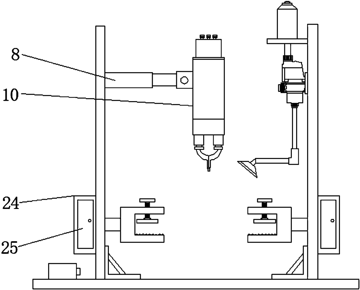
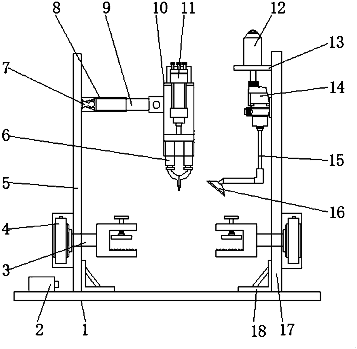
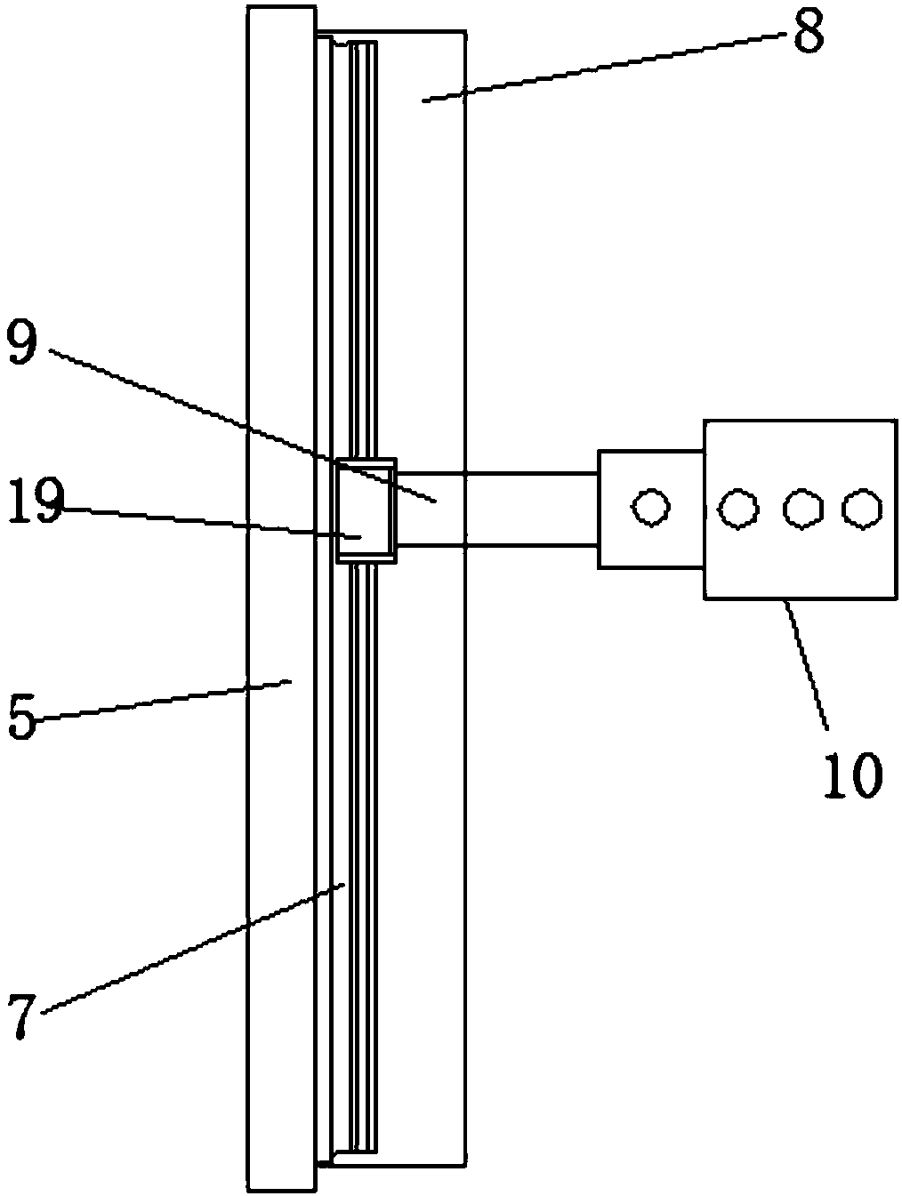
[0017] see Figure 1-4 , an embodiment provided by the present invention: a welding device for improving efficiency, comprising a base plate 1, a motor compartment 24, an installation compartment 8, an installation shell 10, and an air box 12, and one end above the base plate 1 is equipped with a first installation plate 5, And the other end above the base plate 1 is equipped with a second mounting plate 17, and the motor compartment 24 is provided below the f...


PUM


Abstract

The invention discloses welding equipment for improving the efficiency. The welding equipment comprises a bottom plate, motor storehouses, a mounting storehouse, a mounting shell and an air box. A first mounting plate is mounted at one end of the upper portion of the bottom plate. A second mounting plate is mounted at the other end of the upper portion of the bottom plate. The motor storehouses are arranged on the lower portions of the outer sides of the first mounting plate and the second mounting plate correspondingly. Rotating motors are mounted in the motor storehouses correspondingly. Rotating shafts are mounted at the output ends of the rotating motors. U-shaped clamping plates are mounted at the ends, away from the rotating motors, of the rotating shafts. According to the welding equipment, an iron plate can be clamped through the U-shaped clamping plates, welding surfaces are rotated and adjusted through the rotating motors, and thus welding of the iron plate can be more comprehensive; a welding part of the welding device can move on an electromagnetic sliding rail through a mounting rod, so that an electric welding machine is moved, and the welding position is adjusted; and the welding device can adjust the height of the electric welding machine through an air cylinder, the automation degree is high, and using is convenient.

Description

technical field [0001] The invention relates to the technical field of welding equipment, in particular to a welding equipment with improved efficiency. Background technique [0002] The welding device is a device that uses the high-temperature arc generated when the positive and negative poles are short-circuited in an instant to melt the solder on the electrode and the material to be welded. The purpose is to combine the objects to be contacted. Similarly, the iron plate welding device uses high temperature It is a device that melts the solder of the welding rod and the welding position of the iron plate, so that the iron plates are combined with each other. The current iron plate welding equipment needs to be operated by hand-held welding machines, and manual adjustment of the welding surface is required. It is inconvenient to use, and the current welding device It is difficult for the welding machine to adjust the position of the material when welding the material, it is...

Claims


Application Information

Patent Timeline
IPC IPC(8): B23K9/16B23K9/32B23K9/28B23K37/04B23K37/047
CPCB23K9/16B23K9/28B23K9/32B23K9/325B23K37/0408B23K37/047
Inventor 钟丽菊
Owner 钟丽菊
Why Eureka
Try Eureka