3D (Three Dimensional) molding device and method of DMD (Digital Mirror Device) scanning imaging

A scanning imaging and molding device technology, applied in the field of 3D printing, can solve the problems of molding precision impact, molding size limitation, etc., and achieve the best technical and practical effects

Pending Publication Date: 2018-07-24
ZHONGSHAN AISCENT TECH
View PDF0 Cites 4 Cited by
  • Summary
  • Abstract
  • Description
  • Claims
  • Application Information

AI Technical Summary

Problems solved by technology

[0002] The existing light-curing 3D molding machines based on DMD (Digital Micromirror Device) are all based on static graphic projection. The basic principle is projector technology, and the molding size is greatly limited in the pursuit of high precision. To achieve large-scale molding, it is necessary to expand the projected spot area, which will seriously affect the molding accuracy

Method used


Image

  • 3D (Three Dimensional) molding device and method of DMD (Digital Mirror Device) scanning imaging
  • 3D (Three Dimensional) molding device and method of DMD (Digital Mirror Device) scanning imaging
  • 3D (Three Dimensional) molding device and method of DMD (Digital Mirror Device) scanning imaging

Examples


Embodiment Construction

[0019] The scheme of this application is further described in conjunction with the accompanying drawings as follows:

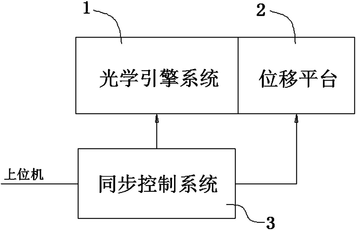
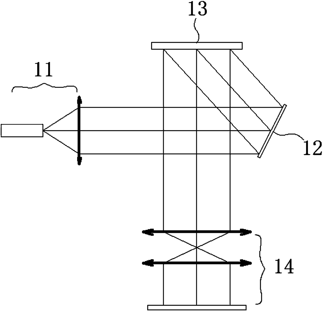
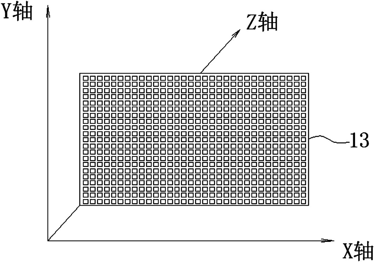
[0020] See attached Figures 1 to 4 , a 3D molding device for DMD scanning imaging, which includes an optical engine system 1, a displacement platform 2 and a synchronous control system 3, the displacement platform 2 has three-axis motion directions of X, Y and Z, and the optical engine system 1 is fixed The displacement on the XY plane is realized on the displacement platform 2, which includes a light source 11, a reflector 12, a DMD array 13 and a scanning lens 14; the displacement platform 2 and the optical engine system 1 are controlled in linkage by the synchronous control system 3, The synchronous control system 3 is connected to a host computer to acquire action instructions and execute them. The DMD array 13 is facing the scanning lens 14, and the light source 11 establishes an optical path to the DMD array 13 through the reflector 12. The light sourc...


PUM


Abstract

The invention provides a 3D (Three Dimensional) molding device and method of DMD (Digital Mirror Device) scanning imaging. The 3D molding device comprises an optical engine system, a displacement platform and a synchronous control system, wherein the optical engine system is fixed on the displacement platform to realize displacement in an XY plane and comprises a light source, a reflection mirror,a DMD array and a scanning lens; the displacement platform and the optical engine system are subjected to linked control by the synchronous control system. The method comprises the following steps: controlling the optical engine system to move along X, Y and Z axes through the displacement platform, wherein the Z axis is a printing height direction; carrying out graph slicing and layered treatment along a height direction of a graph; carrying out graph partitioning on the layered graph in the X direction according to the effective width d of DMD, so as to obtain each graph width d; scanning the partitioned graph in the height direction of the DMA one by one. According to the 3D molding device and method, provided by the invention, the defects that an existing 3D printing technology basedon a DMD projection technology cannot realize large-size and high-precision printing at the same time are overcome; the 3D molding device and method have relatively good technical characters and practicability and is suitable for being popularized and applied.

Description

technical field [0001] The invention belongs to the field of 3D printing, and in particular relates to a 3D forming device and method for DMD scanning imaging. Background technique [0002] The existing light-curing 3D molding machines based on DMD (Digital Micromirror Device) are all based on static graphic projection. The basic principle is projector technology, and the molding size is greatly limited in the pursuit of high precision. To achieve large-scale molding, it is necessary to expand the projected spot area, which will seriously affect the molding accuracy. Contents of the invention [0003] In order to solve the problem of limited precision and size in the field of 3D printing, the present invention proposes a 3D forming device for DMD scanning imaging, and its specific technical content is as follows: [0004] A 3D forming device for DMD scanning imaging, which includes an optical engine system, a displacement platform and a synchronous control system, the dis...

Claims


Application Information

Patent Timeline
IPC IPC(8): B29C64/129B29C64/264B33Y30/00
CPCB33Y30/00B29C64/245B29C64/393B33Y50/02
Inventor 徐珍华阮立锋唐战备杨小红
Owner ZHONGSHAN AISCENT TECH
Why Eureka
Try Eureka