

Miniaturized high-gain double-frequency WIFI antenna
A high-gain, antenna technology, applied in antennas, antenna arrays, resonant antennas, etc., can solve the problems of low gain and large size of WIFI antennas, achieve miniaturization design, overcome large size, small gain and small omnidirectionality
- Summary
- Abstract
- Description
- Claims
- Application Information
AI Technical Summary
Problems solved by technology
Method used
Image

Examples
Embodiment 1
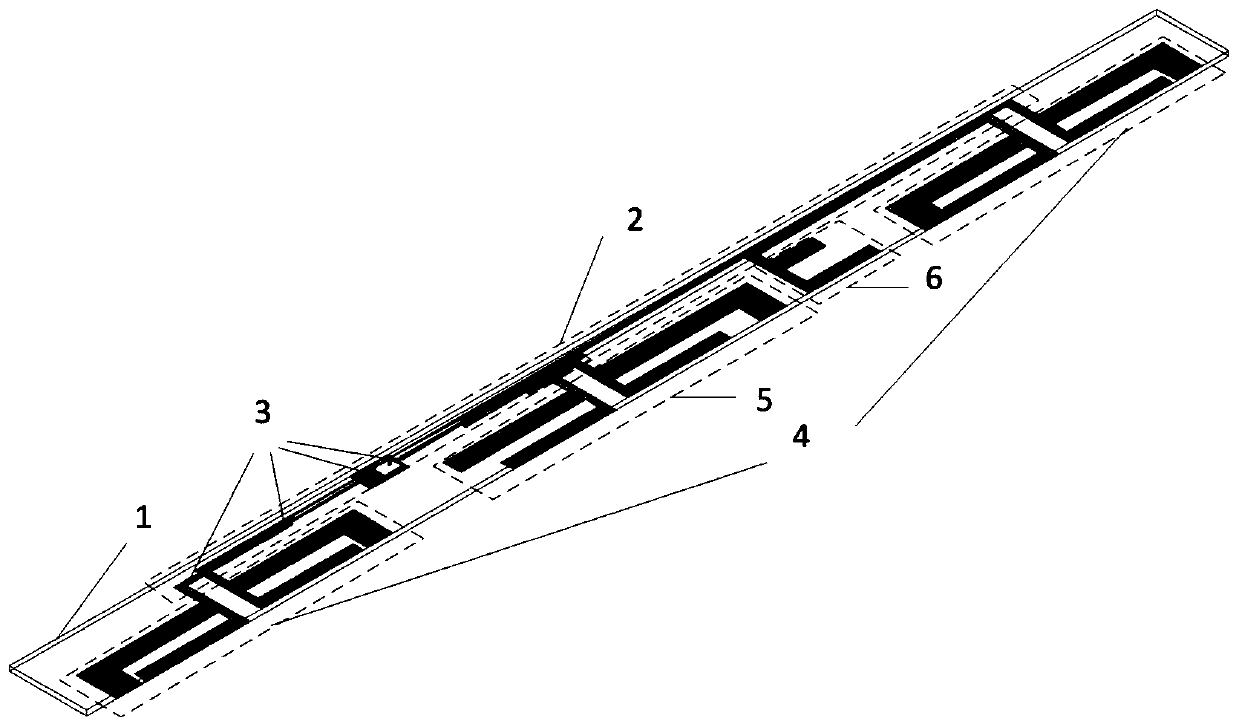
[0035] Refer to attached figure 1 , attached figure 2 , attached image 3 , attached Figure 4 , attached Figure 5 And attached Image 6
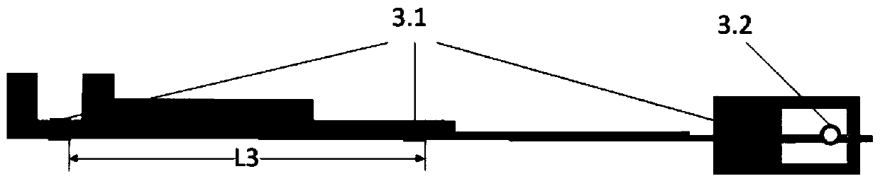
[0036] A miniaturized high-gain dual-band WIFI antenna, including a dielectric plate 1, a microstrip feed network 2, a pad 3, two symmetrical dipole radiating elements 4, an asymmetrical dipole radiating element 5 and "u" Shaped branch 6, the pad 3 is composed of three identical rectangular pads 3.1 and an annular pad 3.2;
[0037]The microstrip feed network 2 includes a ladder-shaped microstrip line 2.1 printed on the upper layer of the dielectric board 1 and a ladder-shaped microstrip line 2.2 on the lower layer; the two symmetrical dipole units 4 are respectively located at both ends of the dielectric board 1; Each symmetrical dipole unit 4 includes two dipole arms 4.1 of the same structure printed on the upper and lower layers of the dielectric board 1, the dipole arms 4.1 are composed of the first low-frequency branch 4.1.1 and...
Embodiment 2
[0049] This embodiment has the same structure as Embodiment 1, only the following parameters are adjusted:
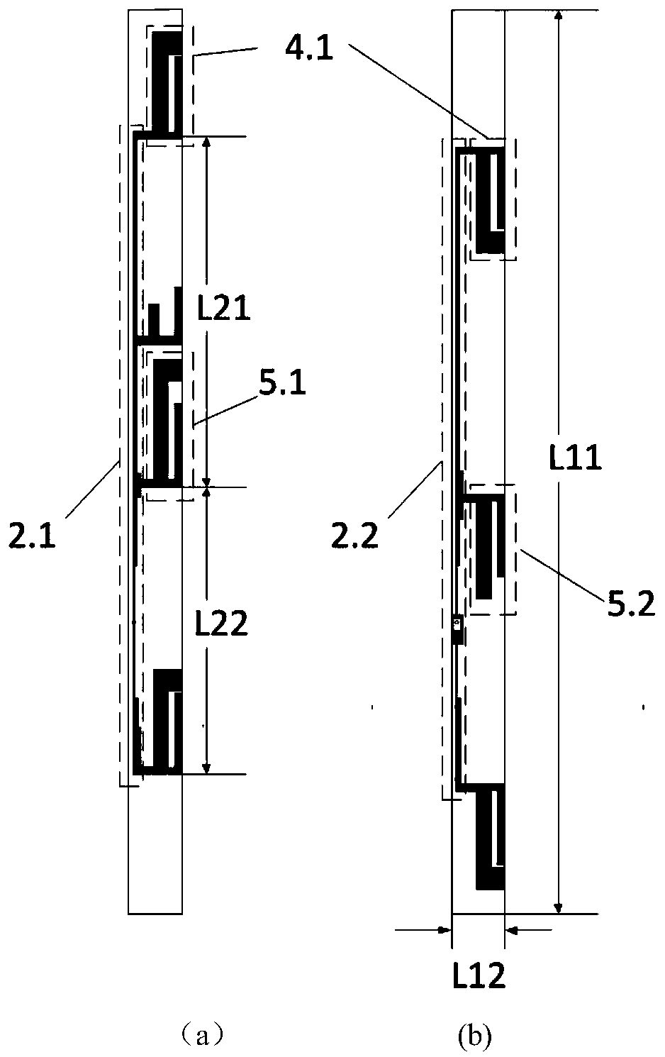
[0050] The length and width of the dielectric board 1 are L11 and L12 respectively, wherein, L11=166-170mm, L12=9-13mm, L11=166mm, L12=9mm.
[0051] The distances between the upper dipole arms 4.1 of the two symmetrical dipole units 4 and the upper dipole arms 5.1 of the asymmetric dipole unit 5 are L21 and L22 respectively, wherein L21=63~67mm , L22=52~56mm, L21=63mm, L22=52mm.
[0052] The lengths of the first low-frequency branch 4.1.1 and the first high-frequency branch 4.1.2 are L41 and L42 respectively, wherein, L41=17.3-19.3mm, L42=12-14mm, L41=17.3mm, L42=12mm ; The width of the first low-frequency branch 4.1.1 is L43, wherein, L43=4.3-6.3mm, L43=4.3mm.
[0053] The lengths of the second low-frequency branch 5.1.1 and the second high-frequency branch 5.1.2 are L51 and L52 respectively, wherein L51=21.3-23.3mm, L52=12-14mm, L51=21.3mm, L52=12mm; The lengths of...
Embodiment 3
[0057] The length and width of the dielectric board 1 are L11 and L12 respectively, wherein L11=166-170mm, L12=9-13mm, L11=170mm, L12=13mm.
[0058] The distances between the upper dipole arms 4.1 of the two symmetrical dipole units 4 and the upper dipole arms 5.1 of the asymmetric dipole unit 5 are L21 and L22 respectively, wherein L21=63~67mm , L22=52~56mm, L21=67mm, L22=56mm.
[0059] The lengths of the first low-frequency branch 4.1.1 and the first high-frequency branch 4.1.2 are L41 and L42 respectively, wherein, L41=17.3-19.3mm, L42=12-14mm, L41=19.3mm, L42=14mm ; The width of the first low-frequency branch 4.1.1 is L43, wherein, L43=4.3-6.3mm, L43=6.3mm.
[0060] The lengths of the second low-frequency branch 5.1.1 and the second high-frequency branch 5.1.2 are L51 and L52 respectively, wherein L51=21.3-23.3mm, L52=12-14mm, L51=23.3mm, L52=14mm; The lengths of the third low-frequency branch 5.2.1 and the third high-frequency branch 5.2.2 are L53 and L54 respectively, ...
PUM
 Abstract
Description
Claims
Application Information