High-low groove type oil-stain floating collection system

A collection system and low tank technology, applied in the field of oil pollution floating collection in high and low tanks, can solve the problems of low oil-water separation efficiency, polluted ground environment, high investment cost, easy later management and maintenance, improved oil-water separation rate, stable operation reliable results

Active Publication Date: 2018-07-24
WUHAN YIYE CONSTR ENG
View PDF6 Cites 1 Cited by
  • Summary
  • Abstract
  • Description
  • Claims
  • Application Information

AI Technical Summary

Problems solved by technology

In addition, the oil generated by the car washing tank at the construction site cannot be collected and separated at any time, and can only be accumulated in the primary sedimentation tank; the conventional primary sedimentation tank uses a fixed overflow port, and when the liquid level drops, the oil layer cannot overflow, and it rains in rainy days Due to the low terrain of the sedimentation tank of the car wash tank, the rainwater is easy to collect and flow into the sedimentation tank in a short time, causing the oily liquid level of the sedimentation tank to rise too fast, and the oil has no time to flow to the collection tank through the fixed overflow port, and it rises from the pool mouth and pollutes the ground environment. The sedimentation tank is often manually adjusted to replenish water, and the collection tank needs to be inspected and pumped every day; moreover, the volume of the sedimentation tank is large, the auxiliary separation device is complex, consumes a lot of energy, is inconvenient to use, and the investment cost is high; more importantly, the efficiency of oil-water separation low

Method used


Image

  • High-low groove type oil-stain floating collection system
  • High-low groove type oil-stain floating collection system
  • High-low groove type oil-stain floating collection system

Examples


Embodiment Construction

[0023] In order to better understand the present invention, the present invention will be further described below in conjunction with the accompanying drawings and specific embodiments.

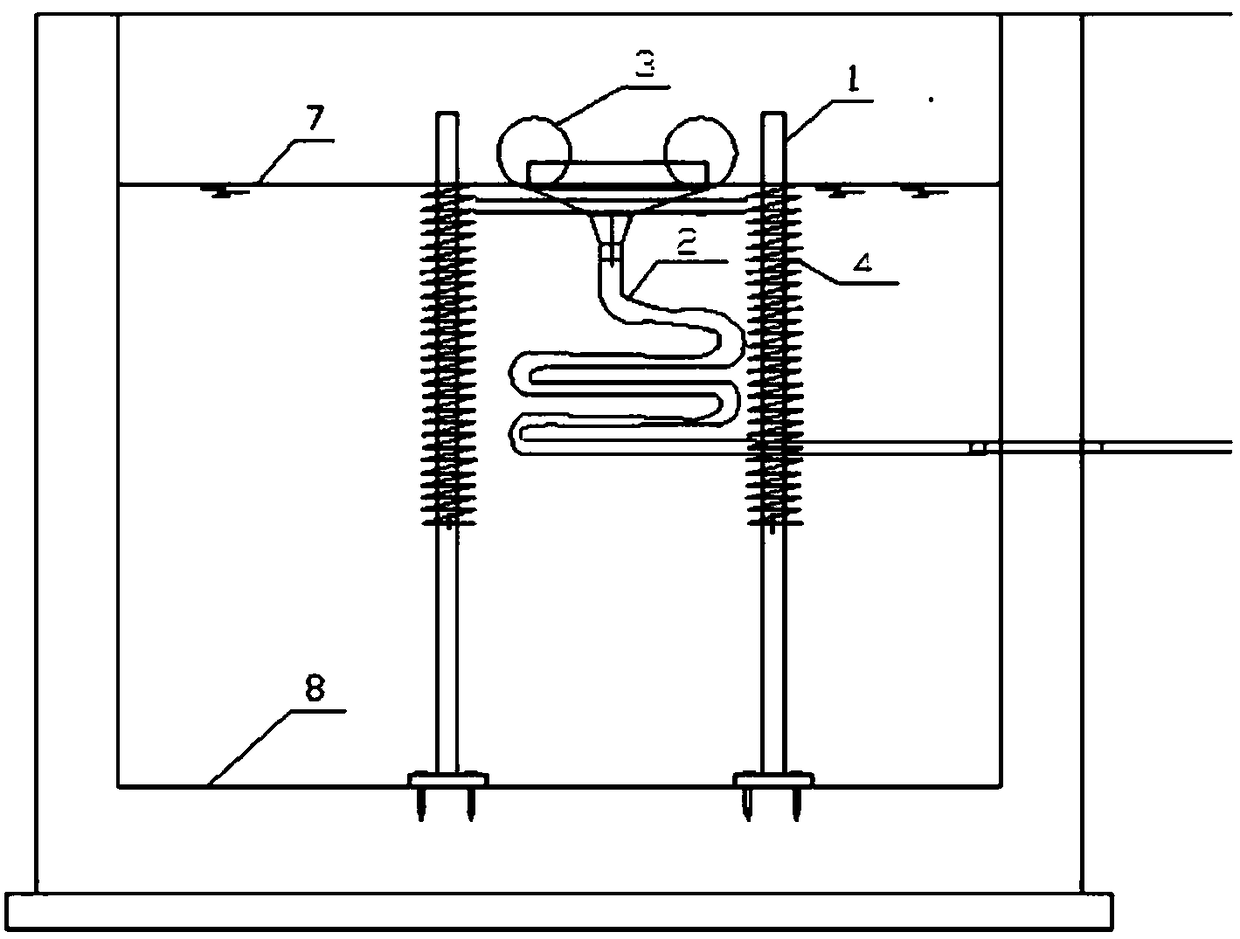
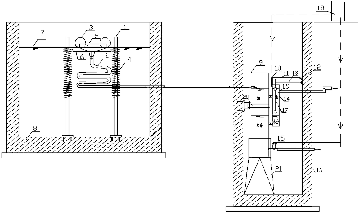
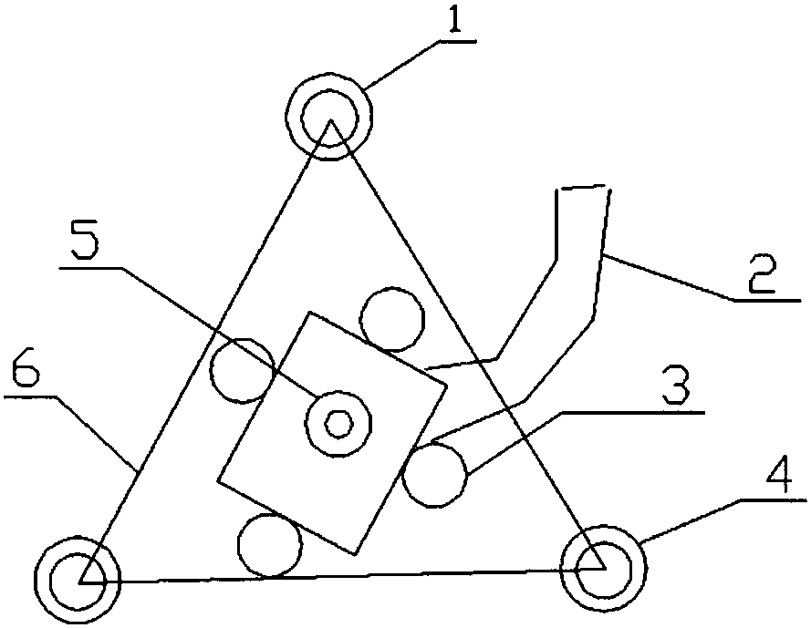
[0024] Such as figure 1 A high and low trough oil floating collection system shown mainly includes a high trough structure and a low trough structure. Such as figure 2 The high groove structure shown mainly includes a high groove base 8, a limiting column 1 and an oil collection conduit 2, the limiting column 1 is arranged in the inner cavity of the high groove base 8, and a flexible spring 4 is set on the upper part of the limiting column 1 (the diameter of the flexible spring 4 is about 20 mm larger than the diameter of the limit column 1), the lower end of the flexible spring 4 is fixedly connected with the limit column 1; the upper end of the flexible spring 4 can move up and down along the limit column 1, and connect with the limit bracket 6 connected; the upper part of the oil collec...


PUM


Abstract

The invention discloses a high-low groove type oil-stain floating collection system. The high-low groove type oil-stain floating collection system mainly comprises a high-groove structure and a low-groove structure, wherein the high-groove structure comprises a high-groove base, limiting vertical columns and an oil-collecting guide pipe; the limiting vertical columns are arranged in an inner cavity of the high-groove base; flexible springs are arranged at the upper parts of the limiting vertical columns; the lower ends of the flexible springs are fixedly connected with the limiting vertical columns; the upper ends of the flexible springs move up and down along the limiting vertical columns; a floating oil-collecting port is arranged in the upper part of the oil-collecting guide pipe and isconnected with the flexible springs; an outlet of the oil-collecting guide pipe is communicated with the low-groove structure; the low-groove structure comprises a low-groove base, a low-groove oil-collecting container, a floater liquid-level meter and a water discharging pipe. The high-low groove type oil-stain floating collection system disclosed by the invention has the beneficial effects thatby adoption of the high-low groove design, initial oil-water separation and floating collection are carried out in a high groove, and secondary oil-water separation is adopted in a low groove, so that the problem that the oil stains carry a large amount of water during oil-water separation in the existing collection equipment and method is solved.

Description

technical field [0001] The invention relates to oil pollution collection and treatment technology, in particular to a floating collection method for oil pollution in high and low tanks. Background technique [0002] At present, there are mainly two methods for oil-water separation, one is physical separation, and the other is chemical separation. These two methods have their own advantages and disadvantages. In addition, the oil generated by the car washing tank at the construction site cannot be collected and separated at any time, and can only be accumulated in the primary sedimentation tank; the conventional primary sedimentation tank uses a fixed overflow port, and when the liquid level drops, the oil layer cannot overflow, and it rains in rainy days Due to the low terrain of the sedimentation tank of the car wash tank, the rainwater is easy to collect and flow into the sedimentation tank in a short time, causing the oily liquid level of the sedimentation tank to rise to...

Claims


Application Information

Patent Timeline
IPC IPC(8): C02F1/40B01D17/025B01D17/032
CPCB01D17/0208B01D17/0214C02F1/40
Inventor 刘黎明廖红玉
Owner WUHAN YIYE CONSTR ENG
Why Eureka
Try Eureka