Joint device of underground diaphragm wall and construction method thereof

A technology of underground diaphragm wall and joint device, which is applied in the direction of sheet pile wall, foundation structure engineering, construction, etc., can solve problems such as the hidden danger of water leakage at the joint of underground diaphragm wall, achieve convenient docking installation and positioning, solve the hidden danger of water leakage, and facilitate The effect of installation and removal

Active Publication Date: 2020-10-13
CHINA CONSTR EIGHT ENG DIV CORP LTD
View PDF4 Cites 0 Cited by
  • Summary
  • Abstract
  • Description
  • Claims
  • Application Information

AI Technical Summary

Problems solved by technology

[0004] The purpose of the present invention is to overcome the defects of the prior art, to provide a joint device for an underground diaphragm wall and its construction method, and to solve the problem in the prior art that the joints of the diaphragm wall are not compact and have hidden dangers of water leakage

Method used


Image

  • Joint device of underground diaphragm wall and construction method thereof
  • Joint device of underground diaphragm wall and construction method thereof
  • Joint device of underground diaphragm wall and construction method thereof

Examples


Embodiment Construction

[0034] The present invention will be further described below in conjunction with the accompanying drawings and specific embodiments.

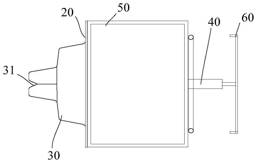
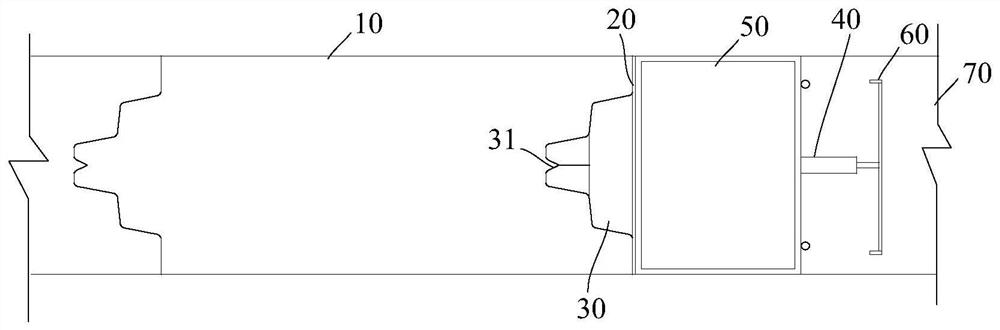
[0035] refer to figure 1 , shows a schematic structural view of the joint device of the underground continuous wall of the present invention. refer to figure 2 , shows a top view of the joint device of the underground continuous wall of the present invention installed in the groove section. combine figure 1 and figure 2 As shown, in general, the underground diaphragm wall is composed of many wall sections. In order to maintain the continuous construction between the wall sections, a trough section with a steel cage is formed first, and the device is fixed at the end of the trough section. , pour concrete into the groove section to form a wall section, take out the device after the initial setting, thereby forming a joint groove on the wall section, so that the adjacent wall section can be spliced ​​through the joint groove and the wall se...


PUM


Abstract

The invention relates to a joint device of an underground continuous wall and a construction method of the joint device. The joint device comprises a baffle which allows to be arranged in a pouring space of the underground continuous wall in an inserted mode and serves as a side formwork of the underground continuous wall, a protruding structure which is fixedly arranged at the position, close tothe inner side face of the pouring space of the underground continuous wall, of the baffle, and a dead shore structure arranged at the position, away from the outer side face of the pouring space of the underground continuous wall, of the baffle in a dead shore mode; and the protruding structure is provided with a mounting groove used for fixing of water stop pieces, the dead shore structure is adjusted in a retractable mode, and the baffle tightly abuts against the end side of the poured underground continuous wall in a vertical shape by retractably adjusting the length of the dead shore structure. The pouring quality is ensured, a joint groove is reserved and formed in the underground continuous wall by using the protruding structure, butt-joint mounting and positioning are facilitated,tight connection is endured, and water leakage is prevented.

Description

technical field [0001] The invention relates to the field of building construction, in particular to a joint device for an underground continuous wall and a construction method thereof. Background technique [0002] The underground diaphragm wall is composed of many wall sections. In order to maintain the continuous construction between the wall sections, the joints in the prior art adopt the locking pipe technology, that is, before pouring the concrete of the groove section, a The steel pipe with the same diameter and groove width, that is, the lock pipe, is slowly pulled out after the initial setting of the concrete, so that the end forms a semi-tenon-shaped structure. Then the protrusion of the reinforcement cage of the lower sub-ground wall is lowered to connect, and then the two wall sections are poured with concrete to form a whole. [0003] The general practice is to fill stone chips or sandbags to fix the position of the lock pipe after inserting the prefabricated j...

Claims


Application Information

Patent Timeline
Patent Type & Authority Patents(China)
IPC IPC(8): E02D5/18
CPCE02D5/18E02D5/187
Inventor 于海申
Owner CHINA CONSTR EIGHT ENG DIV CORP LTD
Why Eureka
Try Eureka