Concrete composite pile foundation

A concrete composite pile, concrete technology, applied in the direction of foundation structure engineering, protective devices, buildings, etc., can solve the problem of insufficient anti-sinking and pulling performance and anti-dynamic load capacity, poor stability and reliability of building foundations, and anti-sinking and pulling piles It is prone to problems such as loosening and longitudinal sliding, so as to improve the effect of anti-settling ability

Active Publication Date: 2018-07-24
CHONGQING TECH & BUSINESS INST
View PDF5 Cites 5 Cited by
  • Summary
  • Abstract
  • Description
  • Claims
  • Application Information

AI Technical Summary

Problems solved by technology

[0003] In view of this, the purpose of the present invention is to solve the problem that the existing anti-sinking and pulling-out structure is simple, and the anti-sinking and pulling-out piles on the soft soil are easy to loosen and slide longitudinally, and the anti-sinking and pulling-out performance and the dynamic load resistance are insufficient, resulting in the construction foundation Based on the defects and deficiencies of poor stability and reliability, a reasonable structure is provided, and the anti-sinking and uplifting pile on soft soil will not loosen and longitudinally slide, and the anti-settling and pulling-out performance and dynamic load resistance have been improved. A concrete composite pile foundation for soft soil with good stability and reliability of the building foundation

Method used


Image

  • Concrete composite pile foundation
  • Concrete composite pile foundation
  • Concrete composite pile foundation

Examples


Embodiment Construction

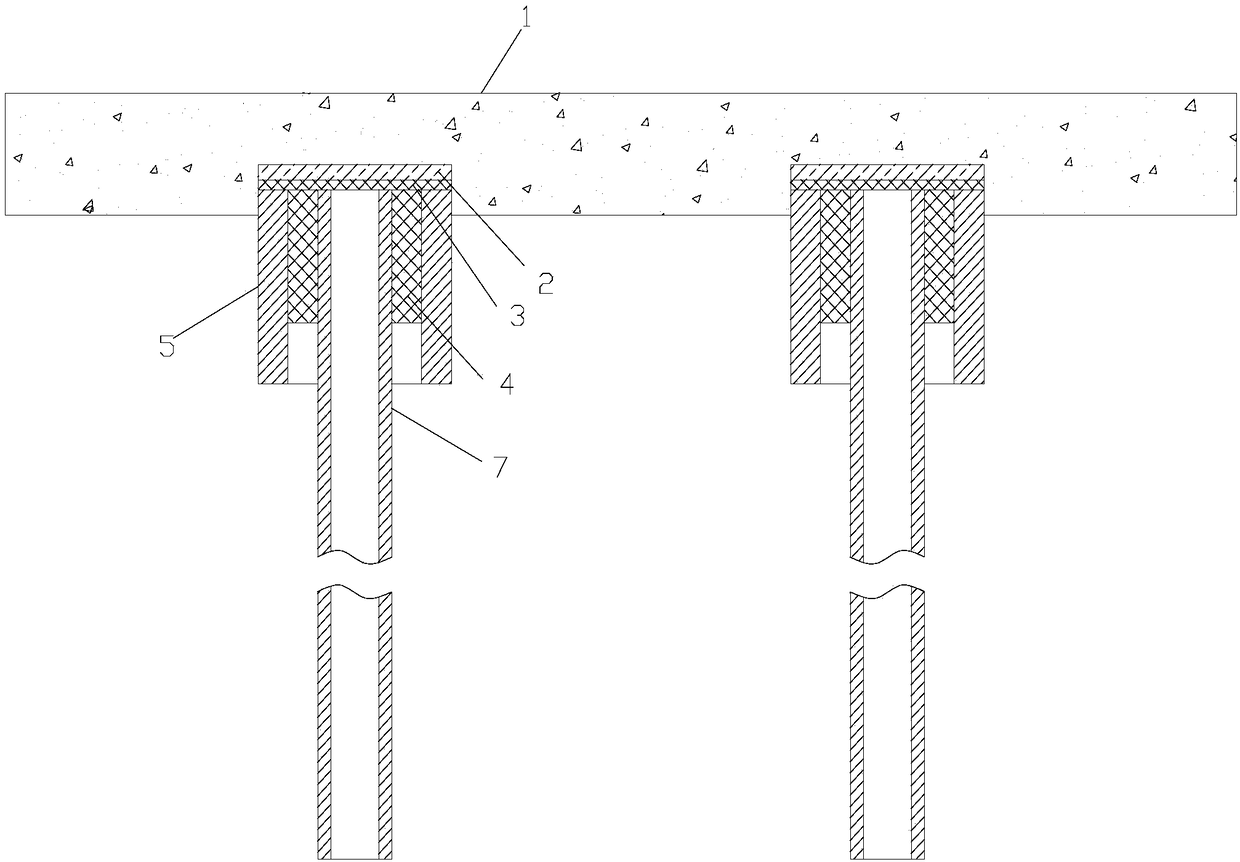
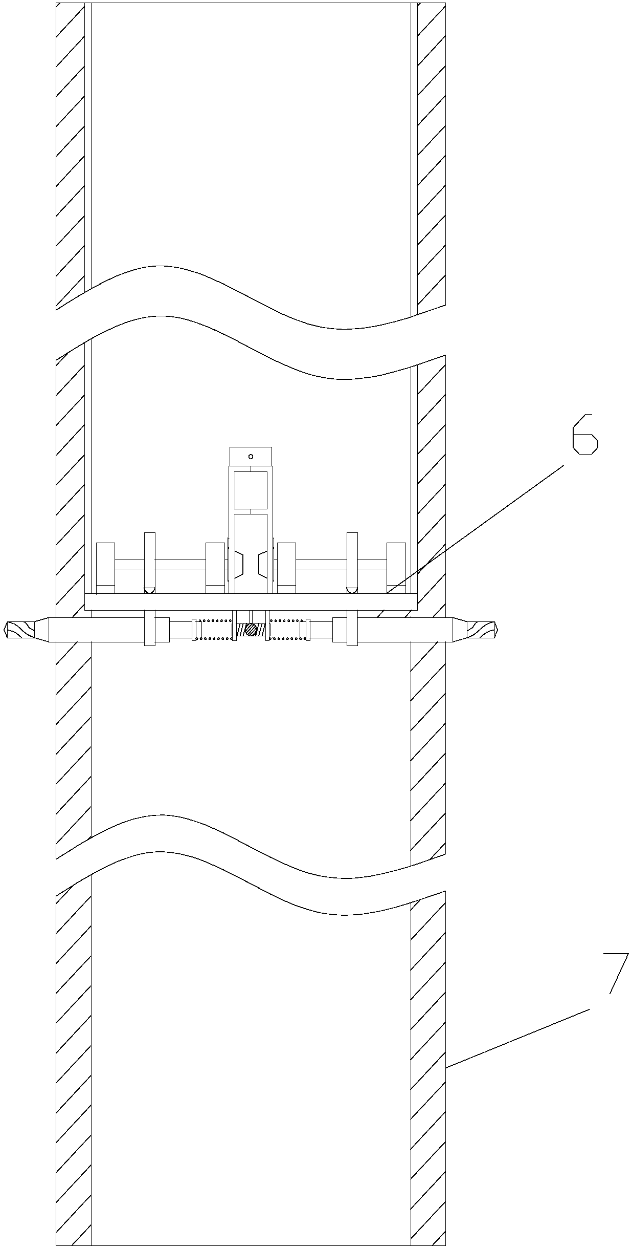
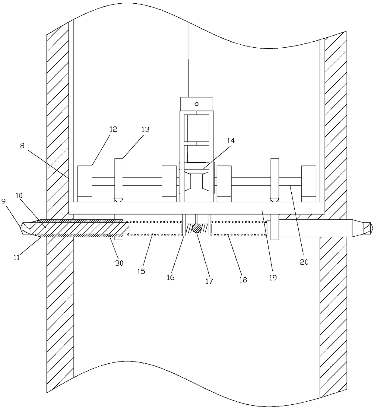
[0022] figure 1 It is a schematic diagram of the structure of the present invention, as shown in the figure: the concrete composite pile foundation of the present embodiment includes an anti-settling pile implanted in the soil layer, a pile cap 5 coaxially sheathed on the top of the anti-settling pile, and supported on the The cap 1 on the top of the pile cap 5; the pile cap 5 is a concrete prefabricated tubular pile, and the pile cap 5 and the anti-settlement pile are filled with concrete 4 for fixing; the described anti-settlement pile includes a pipe body 7, which is arranged on the The anti-settling mechanism 6 in the pipe body 7; the anti-settling mechanism 6 includes four anti-settling rods 11 arranged in a "cross" shape and corresponding to the anti-settling rods 11 one-to-one, used to drive the anti-settling Rod 11 stretches out the four screw nut pairs outside the pipe body 7; the screw mandrel 20 of each said screw nut pair is provided with bevel gear 22; during cons...


PUM


Abstract

The invention discloses a concrete composite pile foundation which comprises an anti-settlement pile buried into a soil layer, a pile cap coaxially arranged outside the top of the anti-settlement pilein a sleeving manner, and a bearing platform supported at the top of the pile cap, wherein the pile cap is a concrete prefabricated tubular pile; a space between the pile cap and the anti-settlementpile is filled with concrete for fixed connection; the anti-settlement pile comprises a steel pipe body and an anti-settlement mechanism arranged in the pipe body; the anti-settlement mechanism comprises four anti-settlement rods arranged in a 'cross' manner and four screw rod and nut pairs which correspond to the anti-settlement rods one to one and are used for driving the anti-settlement rods toextend out of the pipe body; a screw rod of each screw rod and nut pair is provided with a bevel gear. The pile foundation disclosed by the invention is reasonable in structure; looseness and longitudinal sliding during anti-settlement pile pulling on soft soil can be avoided; the anti-settlement pulling performance and the dynamic load resistance are improved.

Description

technical field [0001] The invention relates to the field of pile foundations, in particular to a concrete composite pile foundation. Background technique [0002] At present, a large number of concrete pile foundation structures are used in municipal engineering and house foundations in cities such as plains and seasides. It is difficult to carry out construction on soft soil using traditional methods. It is easy to loosen and slide longitudinally, and there are defects such as insufficient anti-sinking and pulling force, insufficient lateral shearing force and insufficient dynamic load resistance, which directly affect the stability and reliability of the building foundation. In the project "Research on Deformation Mechanism and Settlement Control Technology of High Railway Embankment Slope" declared by the inventor of this application (this project is an open project of the key laboratory of the Ministry of Education jointly established by the Ministry of Education for ro...

Claims


Application Information

Patent Timeline
Patent Type & Authority Applications(China)
IPC IPC(8): E02D27/14E02D31/08
CPCE02D27/14E02D31/08
Inventor 郝笑甜邱小玲刘春波
Owner CHONGQING TECH & BUSINESS INST
Why Eureka
Try Eureka