
High-rise building fire protection structure

A technology for fire-resistant structures and high-rise buildings, which is applied to building components, building structures, and fire prevention. It can solve problems that affect evacuation, affect fire fighting, and insufficient fire water, and achieve the effect of increasing oxygen and preventing fire from spreading.

Inactive Publication Date: 2018-07-24
重庆谦谦装饰工程有限公司
View PDF5 Cites 6 Cited by
  • Summary
  • Abstract
  • Description
  • Claims
  • Application Information

AI Technical Summary

Problems solved by technology

[0005] 2. Difficulty in evacuation
Ordinary elevators stop running due to power cuts and other reasons in the event of a fire. The safe evacuation of most high-rise buildings mainly relies on stairs, and once smoke enters the stairwell, it will seriously affect evacuation.
[0006] 3. It is difficult to save
For example, the fire-fighting water consumption of high-rise buildings is considered according to the current economic and technological level of our country and the general fire scale. When a large-scale fire occurs, the fire-fighting water consumption is obviously insufficient, and it is necessary to use fire trucks to supply water to high-rise buildings. If there is no fire elevator installed, the firefighters cannot reach the fire floor in time to fight the fire, and the fire fighting equipment cannot be replenished at any time, which will affect the fire fighting
[0007] 4. There are many fire hazards
Some high-rise comprehensive buildings have complex functions, many combustibles, and lax fire safety management
For example, some buildings have commercial business halls, combustible warehouses, restaurants, etc.; some office buildings are leased to many units for use, and the safety management is not uniform. Once a fire occurs, it is easy to cause a large area of ​​fire

Method used


Image

  • High-rise building fire protection structure
  • High-rise building fire protection structure
  • High-rise building fire protection structure

Examples


Embodiment Construction

[0025] Further detailed explanation through specific implementation mode below:

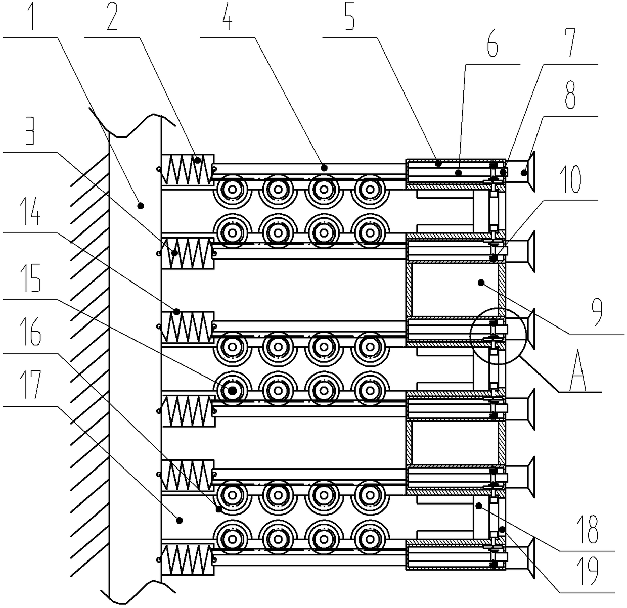
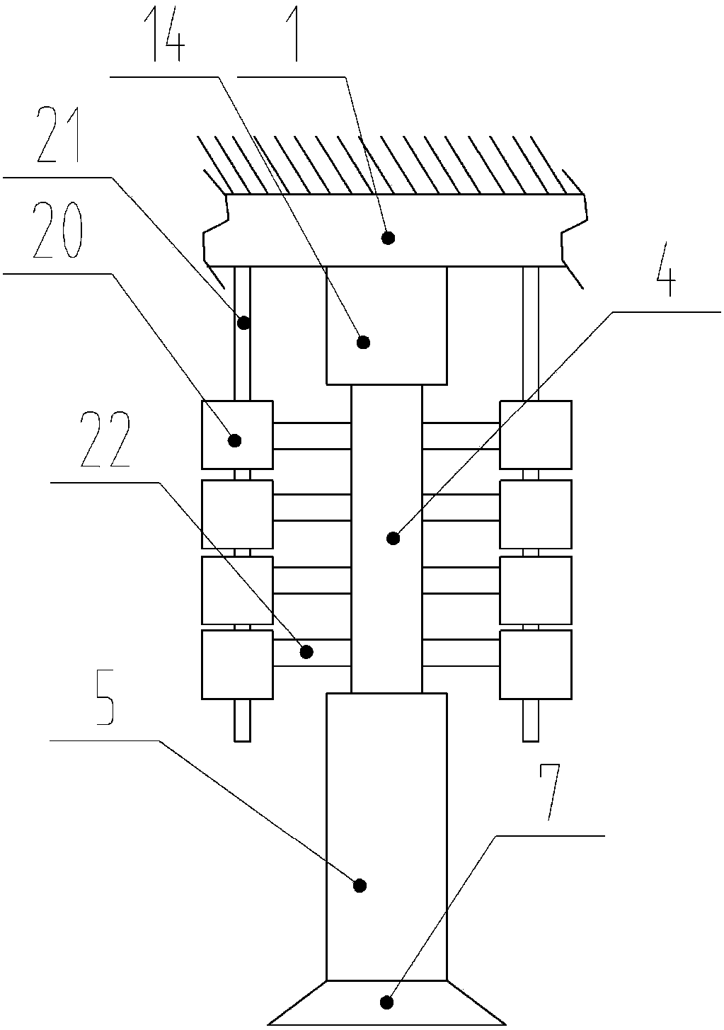
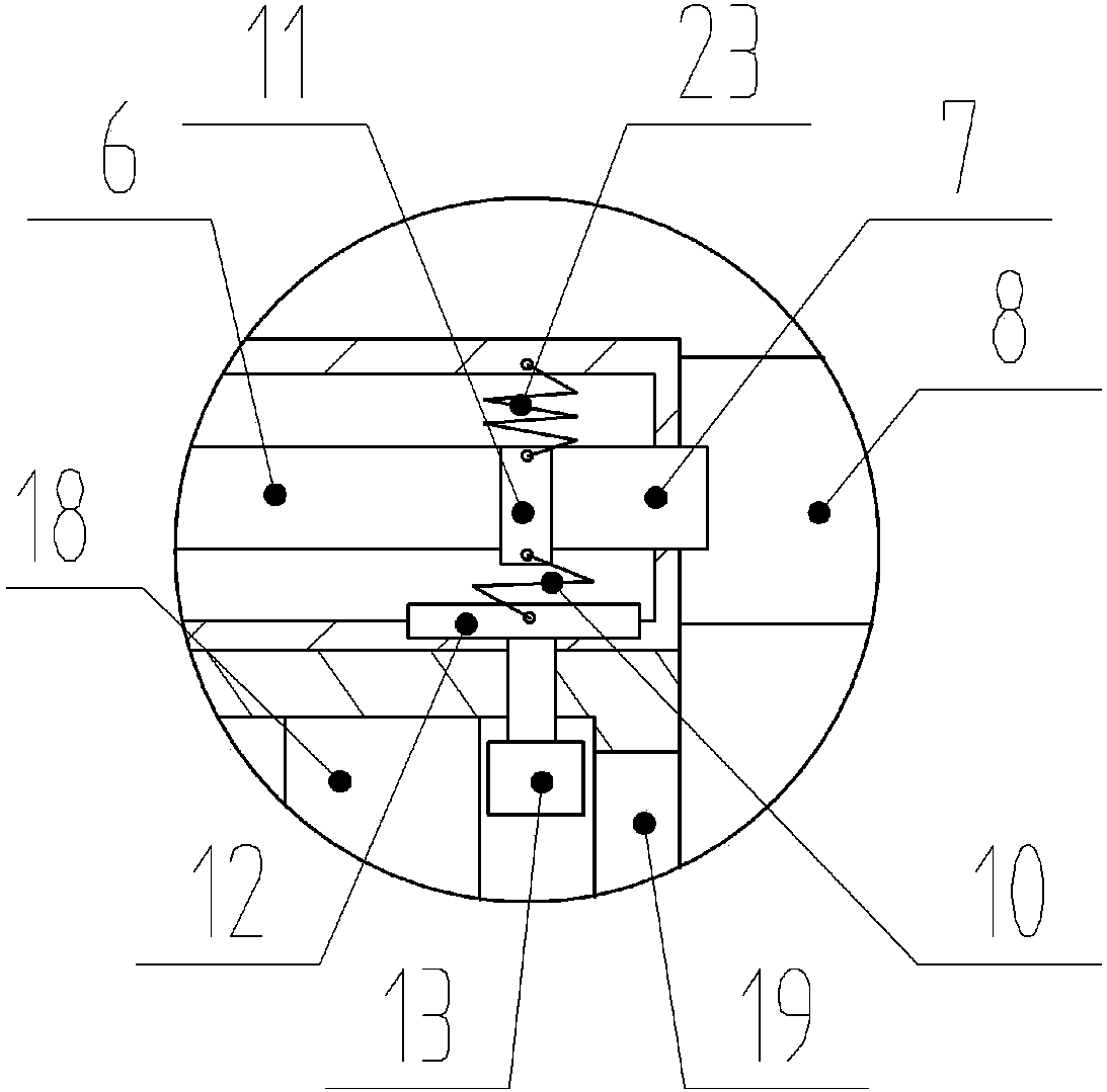
[0026] The reference signs in the drawings of the description include: fixed plate 1, first return spring 2, second return spring 3, rack 4, fire extinguishing pipe 5, aluminum sulfate solution pipe 6, sodium bicarbonate solution pipe 7, spray chamber 8 , smoking box 9, first clip spring 10, movable block 11, moving plate 12, air bag 13, fixed pipe 14, gear 15, movable groove 16, piston rod 17, piston 18, smoking hole 19, stepper motor 20, support Rod 21, output shaft 22, second compression spring 23.

[0027] Note: The up, down, left, and right in this embodiment are subject to the up, down, left, and right of the drawings.

[0028] The fireproof structure of a high-rise building in the embodiment of the present invention is arranged in several lines according to the height and the number of floors of the high-rise building body. The location of the fireproof structure of high-rise buildings c...


PUM


Abstract

The invention discloses a high-rise building fire protection structure comprising a fixed plate, a flue gas absorbing box and a plurality of pushing units arranged on the fixed plate. The fixed plateis connected with the flue gas absorbing box through the pushing units, and the pushing units comprise piston rods, piston chambers arranged in the flue gas absorbing box and two fire extinguishing tubes; racks and fixed tubes of a hollow structure are arranged at the upper and lower sides of the piston rods; one ends of the fixed tubes are fixed on the fixed plate, and the other ends of the fixedtubes are detachably connected with the racks; the fire extinguishing tubes are provided with spray nozzles located on the outer side of the flue gas absorbing box, and the fire extinguishing tubes are internally provided with aluminum sulfate solution tubes and sodium bicarbonate solution tubes; the aluminum sulfate solution tubes and the sodium bicarbonate solution tubes are symmetrically arranged, and movable blocks are arranged between the aluminum sulfate solution tubes and the sodium bicarbonate solution tubes; second compression springs connected to the inner walls of the fire extinguishing tubes are arranged at the upper ends of the movable blocks; and air bags are arranged on the inner walls of the piston chambers for pushing the movable blocks to move, the air bags are filled with nitrogen gas, and therefore fire spreading is prevented.

Description

technical field [0001] The invention belongs to the technical field of fire-fighting facilities, in particular to a high-rise building fire-proof structure. Background technique [0002] According to the "Regulations on Fire Protection Design of High-rise Civil Buildings", high-rise civil buildings refer to residential buildings with ten floors or more (including residential buildings with commercial service outlets on the first floor) and public buildings with a building height of more than 24 meters. With the development of the national economy and society, the process of urbanization is getting faster and faster, and more and more people are flocking to the cities. In the cities where there are many high-rise buildings, the buildings are getting taller and taller. In the blink of an eye, in Beijing, Shanghai and other big cities In the middle of the city, tall buildings have sprung up like mushrooms after rain. High-rise buildings with cutting-edge appearance and luxurio...

Claims


Application Information

Patent Timeline
IPC IPC(8): E04B1/94A62C31/02A62C2/06A62C5/00
CPCE04B1/94A62C2/06A62C5/004A62C31/02E04B1/946
Inventor 张谦
Owner 重庆谦谦装饰工程有限公司
Learn More