Ultra-high pressure balanced load balancing valve and method thereof

An ultra-high pressure and balanced technology, applied in the field of hydraulic control valves, can solve the problems of increased load of the jacking cylinder, partial load, structural damage of the workpiece, etc., and achieve the effect of increasing the load capacity and improving the economy.

Pending Publication Date: 2018-07-24
无锡市思进工业自动化设备有限公司
View PDF0 Cites 4 Cited by
  • Summary
  • Abstract
  • Description
  • Claims
  • Application Information

AI Technical Summary

Problems solved by technology

[0002] When multiple (4 or more) oil cylinders are used to lift a heavy object, there are usually problems with synchronization and load balancing, especially when the oil cylinder is lowered with load, it is more likely to be overloaded; that is, one oil cylinder descends slightly faster , most of the load will be pressed on the two cylinders on the other diagonal, which will nearly double the pressure of the cylinder. In order to ensure the safety of the cylinder, the load capacity of the cylinder has to be reduced by one time. For example: top It is not economical to use at least four 500-ton oil cylinders to lift a 1,000-ton workpiece. At the same time, overloading will cause local structural damage to the workpiece.
[0003] In the prior art, the four-point lifting hydraul

Method used


Image

  • Ultra-high pressure balanced load balancing valve and method thereof
  • Ultra-high pressure balanced load balancing valve and method thereof
  • Ultra-high pressure balanced load balancing valve and method thereof

Examples


Embodiment 1

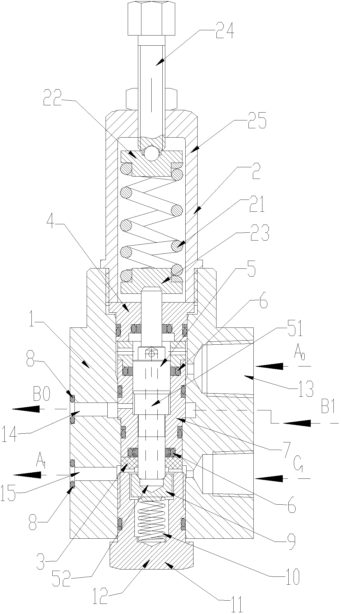
[0036] Such as figure 1 The illustrated ultra-high pressure balanced load equalizing valve of the present invention includes a valve cavity arranged in the valve body 1 and communicated with the outside up and down. The valve cavity is preferably cylindrical as a whole, and the valve cavity is fixedly arranged There is a valve sleeve 7, and a spool 5 is movable inside the valve sleeve 7, and the spool 5 can move up and down sealed in the valve sleeve 7, that is, to ensure sealing and move up and down, and the spool 5 Both ends are respectively sleeved with an upper sealing seat 4 and a lower sealing seat 3, the valve core 5 can protrude from the upper sealing seat 4 and the lower sealing seat 3, and its contact surface is sealed and liquid-tight, the upper and lower parts of the valve cavity The ends are respectively sealed with a pressure regulating spring device 2 and a conical valve seat spring device 11. It is used to adjust the pressure of the top pressure valve core 5, ...

Embodiment 2

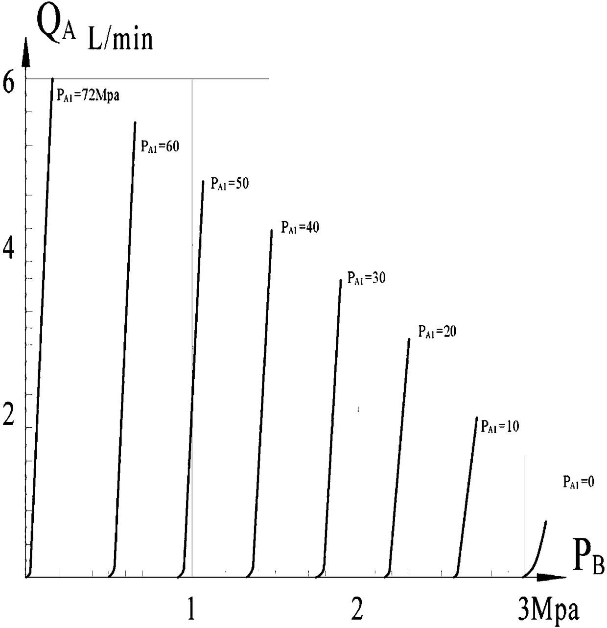
[0043] On the basis of the ultra-high pressure balanced load equalizing valve described in Embodiment 1, the pressure regulating spring device 2 includes a spring cover 25 sealingly arranged on the upper end of the valve cavity, and the spring cover 25 is provided with a pressure regulating spring 21 and the The upper spring seat 22 and the lower spring seat 23 at the two ends of the pressure regulating spring 21, the lower spring seat 23 is pressed against the upper end of the valve core 5, and the upper end of the upper spring seat 22 is provided with an adjusting screw 24, which can be rotated Turn the adjustment screw 24 to adjust the pressure value of the pressure regulating spring 21 to provide different pressure value needs. In the present embodiment, 72 is the set pressure (Mpa) of the ultra-high pressure balance load balancing valve. Therefore, the ultra-high pressure balance equalization The opening condition of the carrier valve can be approximately expressed as: P ...

Embodiment 3

[0052] A balanced load balancing method using the above-mentioned ultra-high pressure balanced load balancing valve, comprising:

[0053] S1: Oil inlet jacking state, such as Figure 4 As shown: Oil flows in from the upper oil port A0, passes through the channel 51 of the valve core 5, pushes the conical valve seat spring device 11, and flows into the lower oil port A1;

[0054] S2: proportional control landing state, such as Figure 6 As shown: oil enters from the pilot control port B0, the black part in the figure is the oil, push the valve core 5 to adjust upward, overcome the pressure regulating spring device 2, and make the valve core 5 and the conical valve seat spring device 11 produce a proportional force The opening makes the pressure oil from the lower oil port A1 flow into the upper oil port A0 proportionally. As the control oil pressure of the pilot control port B0 increases, the proportional opening becomes larger, and the pressure oil from the lower oil port A1 ...


PUM


Abstract

The invention relates to an ultra-high pressure balanced load balancing valve and a method thereof. The ultra-high pressure balanced load balancing valve comprises a valve cavity, wherein the valve cavity is formed in a valve body and an upper part and a lower part of the valve cavity communicates with the outer part of the valve cavity; a valve core is movably arranged in a valve sleeve; an uppersealing base and a lower sealing base are respectively arranged at the two ends of the valve core in a sleeving manner; a pressure adjustment spring device and a conical valve seat spring device arerespectively arranged at the upper end and the lower end of the valve cavity in a sealed manner; an upper hydraulic chamber is arranged between the valve core and the upper sealing base and communicates with an upper oil hole; a lower hydraulic chamber communicates with a lower oil hole; the upper hydraulic chamber communicates with the lower hydraulic chamber through a channel arranged in the valve core; the valve sleeve is also provided with an intermediate hydraulic chamber formed in the middle end of the valve core; and the intermediate hydraulic chamber is connected with a pilot control hole and an oil passing hole. The ultra-high pressure balanced load balancing valve disclosed by the invention is mounted on an oil cylinder, the load balancing valve can be automatically turned on when the pressure in the oil cylinder exceeds the regulated pressure, over-high oil pressure is unloaded, a function of balancing load is achieved when one load is synchronously jacked by a plurality ofoil cylinders, and the oil cylinder is protected from being overloaded and damage on the oil cylinder is avoided, and therefore, the service life of the oil cylinder is prolonged, and the economical efficiency is promoted.

Description

technical field [0001] The invention relates to an ultra-high pressure balanced load equalizing valve and a method thereof, belonging to the technical field of hydraulic control valves. Background technique [0002] When multiple (4 or more) oil cylinders are used to lift a heavy object, there are usually problems with synchronization and load balancing, especially when the oil cylinder is lowered with load, it is more likely to be overloaded; that is, one oil cylinder descends slightly faster , most of the load will be pressed on the two cylinders on the other diagonal, which will nearly double the pressure of the cylinder. In order to ensure the safety of the cylinder, the load capacity of the cylinder has to be reduced by one time. For example: top To lift a workpiece of 1000 tons, at least four 500-ton oil cylinders must be used, which is very uneconomical, and overloading will also cause local structural damage to the workpiece. [0003] In the prior art, the four-poin...

Claims


Application Information

Patent Timeline
IPC IPC(8): F15B13/02F15B20/00F16K17/06
CPCF15B13/02F15B20/005F15B20/007F16K17/06
Inventor 徐文友姜银福吕学华楚刚
Owner 无锡市思进工业自动化设备有限公司
Why Eureka
Try Eureka