Roller chain and chain transmission system

A technology of rollers and chains, which is applied in the field of roller chains and chain transmission systems, can solve the problems of small chain load capacity, poor fatigue resistance and wear resistance, and achieve improved load capacity, tensile performance, and resistance The effect of tensile strength

Pending Publication Date: 2018-07-24
SUZHOU UNIVERSAL GRP TECH CO LTD
View PDF6 Cites 2 Cited by
  • Summary
  • Abstract
  • Description
  • Claims
  • Application Information

AI Technical Summary

Problems solved by technology

[0006] The purpose of the present invention is to provide a roller chain to solve the technical problems in the prior art that the chain has a small load capacity, poor fatigue resistance and wear resistance

Method used


Image

  • Roller chain and chain transmission system
  • Roller chain and chain transmission system
  • Roller chain and chain transmission system

Examples


Embodiment 1

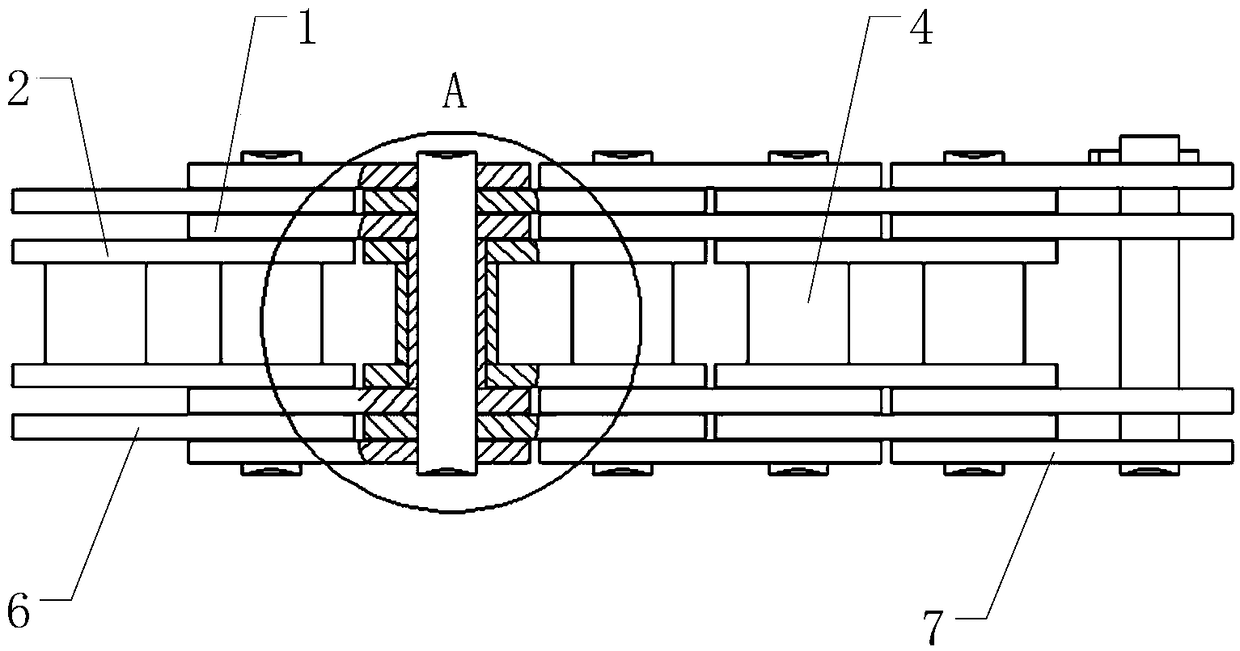
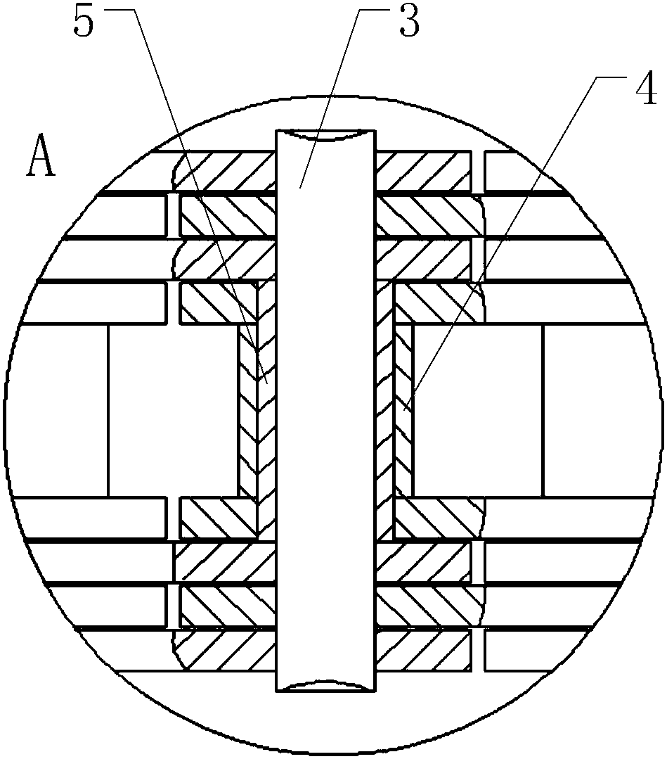
[0044] see Figure 1-Figure 3 shown, where, in order to clearly show the structure, figure 1 The middle part of the structure is shown in a partially sectioned state. This embodiment provides a roller chain, including an outer chain plate 1, an inner chain plate 2, a pin shaft 3, a roller 4, a sleeve 5, a first reinforcing plate 6 and a second reinforcing plate 7;

[0045] Both ends of the sleeve 5 along the axial direction are respectively fixed on the two inner chain plates 2 oppositely arranged; the pin shaft 3 is sleeved in the sleeve 5, and the pin shaft 3 is connected to the shaft The two ends of the direction are connected to the inner link plate 2 through the outer link plate 1, and the pin shaft 3 can rotate relative to the sleeve 5;

[0046] The roller 4 is sleeved outside the sleeve 5, and the roller 4 can rotate relative to the sleeve 5;

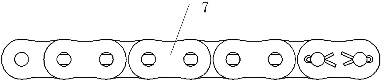
[0047] The first reinforcement plate 6 is arranged on the side of the outer chain plate 1 away from the inner chain plate 2,...

Embodiment 2

[0085] Embodiment 2 provides a chain transmission system, which includes the roller chain described in Embodiment 1. The technical features of the roller chain disclosed in Embodiment 1 are also applicable to this embodiment. Embodiment 1 has The technical features of the disclosed roller chain will not be described repeatedly. The implementation of the chain transmission system will be further described in detail below in conjunction with the accompanying drawings.

[0086] In order to save space, the improved features of this embodiment are also reflected in Figure 1-Figure 3 in, therefore, combined with Figure 1-Figure 3 The configuration of this example will be described.

[0087] see Figure 1-Figure 3 As shown, the chain transmission system provided by this embodiment includes the above-mentioned roller chain.

[0088] It further solves the technical problems in the prior art that the chain has a small load-bearing capacity, poor fatigue resistance and wear resista...


PUM


Abstract

The invention relates to the technical field of transmission components, in particular to a roller chain and a chain transmission system. The roller chain comprises outer chain plates, inner chain plates, pin shafts, rollers, sleeves, first reinforcing plates and second reinforcing plates. The two ends of each sleeve are fixed to the two corresponding inner chain plates arranged oppositely. The pin shafts are sleeved with the corresponding sleeves. The two ends of each pin shaft are connected with the corresponding outer chain plate and the corresponding inner chain plate. The sleeves are sleeved with the corresponding rollers. The first reinforcing plates are arranged on the sides, far away from the inner chain plates, of the corresponding outer chain plates. The first reinforcing platesconnect the two adjacent pin shafts. The second reinforcing plates are arranged on the side, far away from the outer chain plates, of the first reinforcing plates. The second reinforcing plates connect the two adjacent pin shafts. The chain transmission system comprises the roller chain. The roller chain and the chain transmission system are provided for solving the technical problems that a chainis small in bearing capacity and poor in anti-fatigue performance and wear-resisting property in the prior art.

Description

technical field [0001] The invention relates to the technical field of transmission components, in particular to a roller chain and a chain transmission system. Background technique [0002] A roller chain is a type of chain used to transmit mechanical power. It is a type of chain drive and is widely used in household, industrial and agricultural machinery, including conveyors, plotters, printing machines, automobiles, motorcycles, and bicycles. It consists of a series of short cylindrical rollers linked together and driven by a gear called a sprocket, which is a simple, reliable and efficient power transmission device. [0003] The roller chain, including the inner chain plate and the outer chain plate, is in the shape of "8", the thickness A of the inner chain plate is 4 mm, the height L is 24.12 mm, and the waist width K is 17.5 mm; the thickness of the outer chain plate is 4 mm, height is 20.82 mm, waist width is 15 mm; pin diameter is 7.92 mm. [0004] Both the inner ...

Claims


Application Information

Patent Timeline
Patent Type & Authority Applications(China)
IPC IPC(8): F16G13/07F16G15/12
CPCF16G13/07F16G15/12
Inventor 黄伟达张春伟拱建军
Owner SUZHOU UNIVERSAL GRP TECH CO LTD
Why Eureka
Try Eureka