
A straight-through high-pressure rotary joint

A rotary joint, straight-through technology, applied in the direction of pipes/pipe joints/fittings, adjustable connections, passing elements, etc., can solve the problems of easy wear and leakage of seals, improve service life and volume efficiency, and reduce flow resistance. , the effect of reducing wear

Inactive Publication Date: 2019-10-22
LANZHOU UNIVERSITY OF TECHNOLOGY +1
View PDF7 Cites 0 Cited by
  • Summary
  • Abstract
  • Description
  • Claims
  • Application Information

AI Technical Summary

Problems solved by technology

[0005] In order to solve the problems of the conventional hydraulic rotary joints that the seals are easy to wear and the leakage simply increases with the increase of the system pressure, the present invention proposes a straight-through high-pressure rotary joint

Method used


Image

  • A straight-through high-pressure rotary joint
  • A straight-through high-pressure rotary joint
  • A straight-through high-pressure rotary joint

Examples


Embodiment Construction

[0027] The technical solutions of the present invention will be described in detail below in conjunction with the accompanying drawings and specific embodiments.

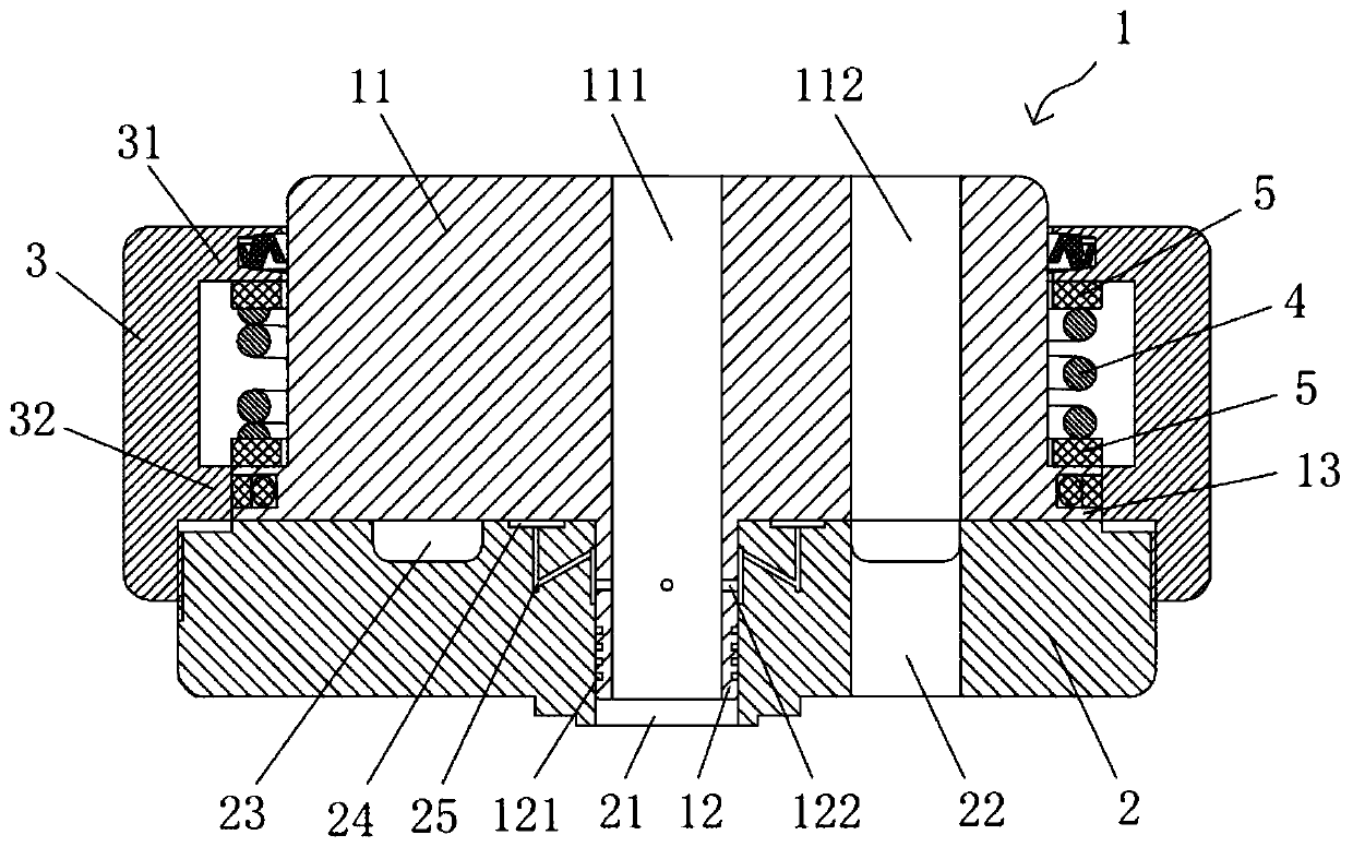
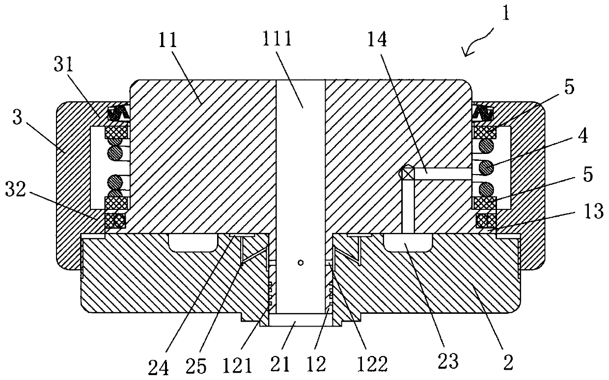
[0028] combine figure 1 As shown, the straight-through high-pressure rotary joint of the present invention includes an upper rotary body 1 , a lower rotary body 2 and a connecting piece 3 . Wherein, the upper rotating body 1 and the lower rotating body 2 can carry out relative movement in the axial direction and relative rotation in the circumferential direction under the connection effect of the connecting member 3 .

[0029] The upper rotating body 1 is a T-shaped structure, including a connecting end 11 located in the upper half and a guiding end 12 located in the lower half. Wherein, a high-pressure oil passage 111 and an upper oil passage 112 are provided on the upper surface of the connection end 11 . A high-pressure oil passage 111 runs through the connection end 11 and the guide end 12 along the central ax...


PUM


Abstract

The invention belongs to the technical field of joint equipment, and particularly relates to a straight-through type high-pressure rotating joint. The straight-through type high-pressure rotating joint aims to solve the problems that in a conventional hydraulic rotating joint, a sealing part is prone to being worn, and the leaking amount is increased along with increase of system pressure. The straight-through type high-pressure rotating joint comprises an upper rotating body, a lower rotating body and a connecting part. The upper rotating body and the lower rotating body can do relative movement in the axial direction and relative rotation in the circumferential direction under the connecting action of the connecting part, and axial static pressure support and axial pre-pressing spring force are set between the upper rotating body and the lower rotating body. According to the straight-through type high-pressure rotating joint, wear to a sealing part can be reduced, the service life can be prolonged, self-adaptive adjustment on system pressure changing can be achieved, the leaking amount can be reduced, and the volume efficiency can be improved.

Description

technical field [0001] The invention belongs to the technical field of joint equipment, and in particular relates to a straight-through high-pressure rotary joint. Background technique [0002] In various hydraulic equipment such as construction machinery, forging machinery, mining machinery, metallurgical machinery, and machine tool industry, rotary joints are often used to transmit hydraulic oil circuits to relatively rotating hydraulic systems to meet actual work needs. [0003] At present, the structure of a conventional hydraulic rotary joint mainly includes an upper rotating body and a lower rotating body, wherein an axial oil channel is provided on the upper rotating body, and an annular oil groove and an oil passage in the upper rotating body are provided on the end surface of the lower rotating body. The channel is connected, and at the same time, a radial oil hole communicating with the annular oil groove is provided on the side of the lower rotating body to realiz...

Claims


Application Information

Patent Timeline
Patent Type & Authority Patents(China)
IPC IPC(8): F16L27/08
Inventor 杨国来曹文斌张志辉安建军张琤琤
Owner LANZHOU UNIVERSITY OF TECHNOLOGY
Learn More