Control box for heater and warmer

A heater and control box technology, which is applied in household heating, heating methods, household heating, etc., can solve problems such as thermal deformation, and achieve the effects of not easy thermal deformation, obvious heat insulation effect, and reduced heat

Active Publication Date: 2018-07-24
GD MIDEA ENVIRONMENT APPLIANCES MFG +1
View PDF6 Cites 1 Cited by
  • Summary
  • Abstract
  • Description
  • Claims
  • Application Information

AI Technical Summary

Problems solved by technology

[0004] One of the objectives of the present invention is to provide a control box and a heater used on a heater, so as to solve the problem of deformation caused by heat when the control box is installed on the heater body in the prior art

Method used


Image

  • Control box for heater and warmer
  • Control box for heater and warmer
  • Control box for heater and warmer

Examples


Embodiment Construction

[0026] In order to understand the above-mentioned purpose, features and advantages of the present invention more clearly, the present invention will be further described in detail below in conjunction with the accompanying drawings and specific embodiments. It should be noted that, in the case of no conflict, the embodiments of the present application and the features in the embodiments can be combined with each other.

[0027] In the description of the present invention, it should be noted that the terms "center", "longitudinal", "transverse", "upper", "lower", "front", "rear", "left", "right", " The orientations or positional relationships indicated by "vertical", "horizontal", "top", "bottom", "inner" and "outer" are based on the orientations or positional relationships shown in the drawings, and are only for the convenience of describing the present invention and Simplified descriptions, rather than indicating or implying that the device or element referred to must have a ...


PUM


Abstract

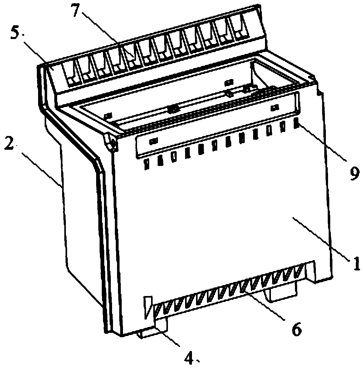
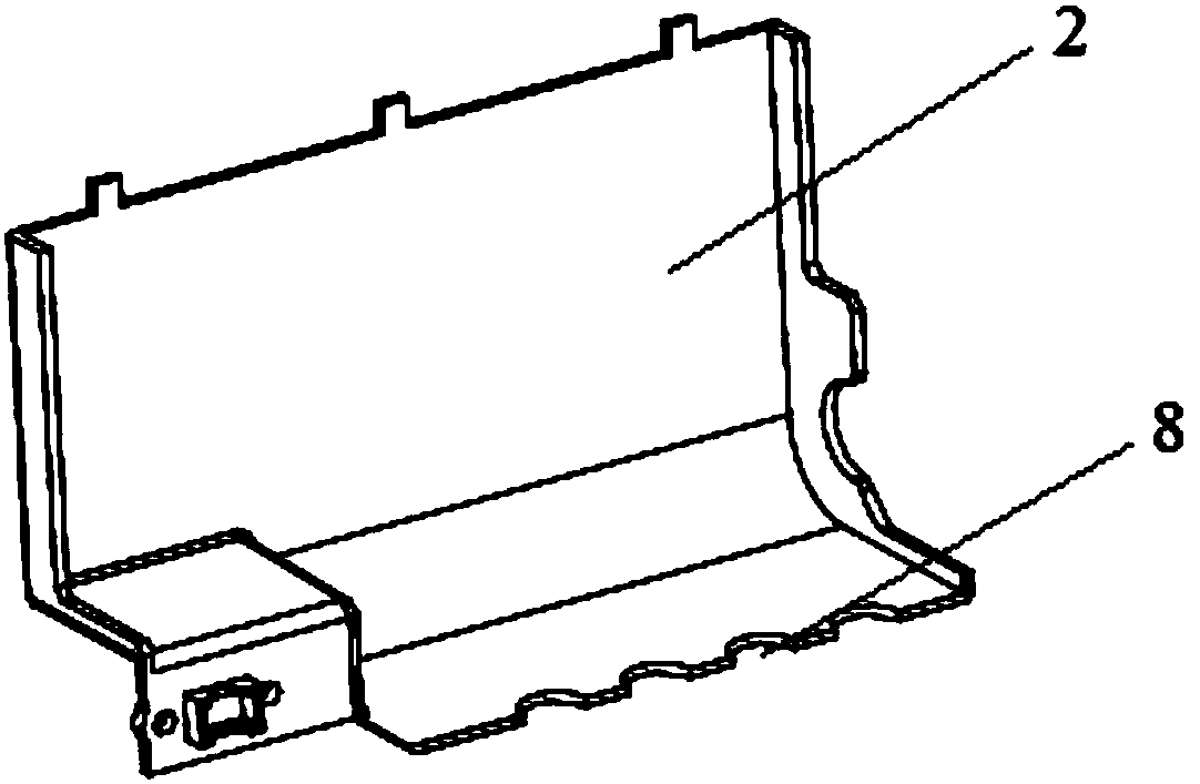
The invention relates to the technical field of heaters and provides a control box for a heater and a warmer. The control box for the heater comprises a protective shell and a control piece located inthe protective shell, wherein the protective shell is used for being installed on an installation plate of the heater body. The side, close to the installation plate, of the protective shell is a heat insulation layer. According to the shape of the heat insulation layer, when the protective shell is installed on the installation plate, a first air flow channel is formed between the heat insulation layer and the installation plate. When the control box for the heater is installed on the heater body, the installation plate of the heater body and the heat insulation layer of the control box achieve dual physical heat insulation, the remarkable heat insulation effect is achieved, so that heat transmitted into the control box from the heater body is greatly reduced, and the temperature of thecontrol box is remarkably lowered. Besides, the air flow channel is formed between the installation plate of the heater body and the heat insulation layer of the control box, so that cooling is more rapid. In this way, the control box for the heater is not prone to generating thermal deformation.

Description

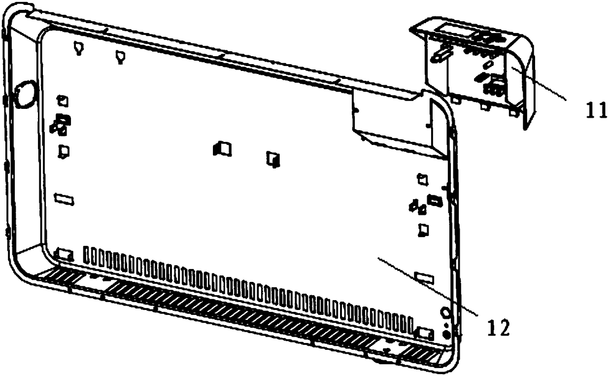
technical field [0001] The invention relates to the technical field of heaters, in particular to a control box used on the heater and a heater. Background technique [0002] figure 1 Shown is a schematic diagram of the installation process of a conventional heater control box, wherein the heater control box is fixed on the rear shell 12 of the heater through buckles and screws. When the heating element of the heater is heated, the hot air rises, and when the heat flows through the control box, it can only be insulated by the steel plate of the rear shell. After such a long period of time, the control box risks being heated and deformed. Contents of the invention [0003] The present invention aims to solve at least one of the technical problems existing in the prior art or related art. [0004] One of the objectives of the present invention is to provide a control box and a heater used on a heater, so as to solve the problem in the prior art that the control box is defo...

Claims


Application Information

Patent Timeline
Patent Type & Authority Applications(China)
IPC IPC(8): F24D19/10H05K7/20
CPCH05K7/20127F24D19/10
Inventor 康宽洋谢新艳高盛华杨鑫温嘉彬陈梓泓
Owner GD MIDEA ENVIRONMENT APPLIANCES MFG
Why Eureka
Try Eureka