Cloth drying mechanism

A cloth drying and cloth guide roller technology, which is applied in the field of cloth manufacturing, can solve the problems of low energy utilization rate, poor drying efficiency, high temperature, etc., and achieve the effect of short distance, high efficiency and high heat utilization rate

Active Publication Date: 2021-09-28
陈方玲
View PDF0 Cites 0 Cited by
  • Summary
  • Abstract
  • Description
  • Claims
  • Application Information

AI Technical Summary

Problems solved by technology

[0002] Cloth needs to go through multiple processes in the production process, among which drying is to remove water from the printed and dyed cloth. In the existing drying process, it is usually only heated in the oven, but the heating method is due to the distance between the cloth and the cloth. Usually far away, resulting in poor drying efficiency, and requires high temperature in the oven, resulting in low energy utilization

Method used


Image

  • Cloth drying mechanism
  • Cloth drying mechanism
  • Cloth drying mechanism

Examples


Embodiment Construction

[0018] In order to enable those skilled in the art to better understand the solutions of the present invention, the technical solutions in the embodiments of the present invention will be clearly and completely described below in conjunction with the drawings in the embodiments of the present invention.

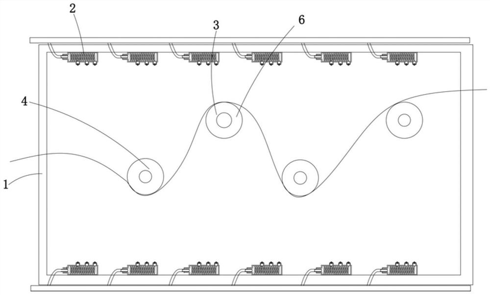
[0019] Such as Figure 1-3 As shown, a cloth drying mechanism includes a box body 1, a heating device 2 and a cloth supporting device 3, the box body 1 is a metal box body, and the heating device 2 is arranged in the box body 1, And the box body 1 is heated, and the heating device 2 is a heating tube composed of a plurality of resistance wires; the cloth supporting device 3 includes a driving roller part 6 and a driven roller part 4, and the driving roller part 6 is A metal roller, which is rotatable by a motor.

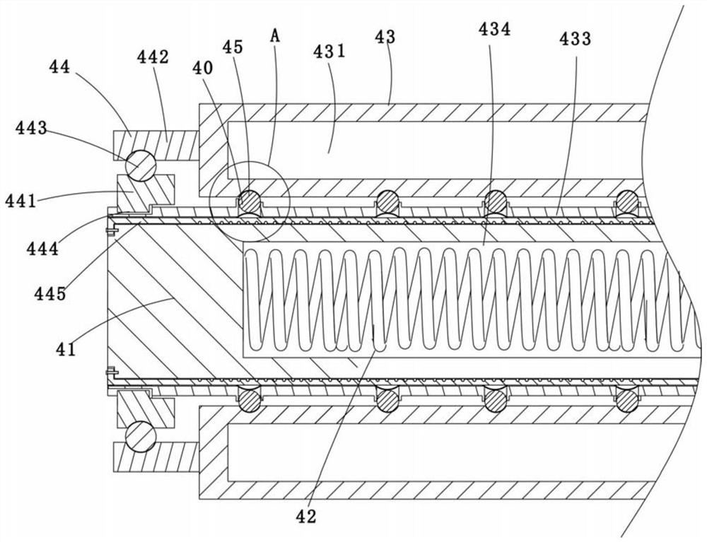
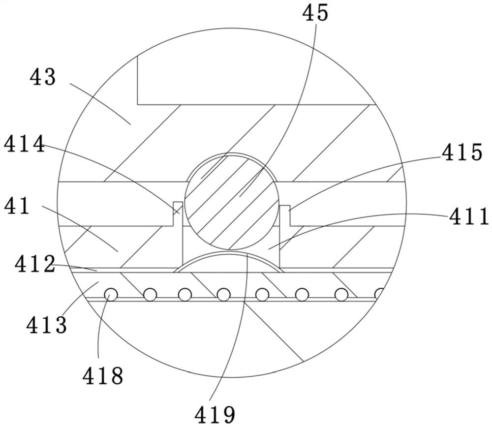
[0020] Further, the driven roller part 4 includes a heat transfer roller 41, a heating element 42 and a cloth guide roller 43, the heating element 42 is a spiral r...


PUM


Abstract

The invention discloses a cloth drying mechanism, which comprises a box body, a heating device arranged in the box body, and a cloth supporting device for supporting the cloth; the cloth supporting device includes a driving roller part and a secondary The driven roller part; the driven roller part includes a heat transfer roller, a heating element passing through the heat transfer roller, and a rotatable cloth guide roller sleeved on the heat transfer roller. In the present invention, the driven roller part is set to heat the cloth and increase the temperature of the cloth; when the arrangement is heated, the distance between the cloth and the cloth is short, the temperature is concentrated, the heat transfer effect is good, the heat utilization rate on the driven roller is improved, and the For the efficiency of heating and drying the cloth, this setting method has low requirements on the temperature in the box, which can effectively save energy.

Description

technical field [0001] The invention belongs to the technical field of cloth manufacturing, and in particular relates to a cloth drying mechanism. Background technique [0002] Cloth needs to go through multiple processes in the production process, among which drying is to remove water from the printed and dyed cloth. In the existing drying process, it is usually only heated in the oven, but the heating method is due to the distance between the cloth and the cloth. It is usually far away, resulting in poor drying efficiency, and requires high temperatures in the oven, resulting in low energy utilization. Contents of the invention [0003] In order to overcome the shortcomings of the prior art, the present invention provides a cloth drying mechanism with high drying efficiency. [0004] In order to achieve the above object, the present invention adopts the following technical solutions: a cloth drying mechanism, including a box body, a heating device arranged in the box bo...

Claims


Application Information

Patent Timeline
Patent Type & Authority Patents(China)
IPC IPC(8): F26B13/08F26B13/18F26B23/06
CPCF26B13/08F26B13/18F26B23/06
Inventor 郑锦锦
Owner 陈方玲
Why Eureka
Try Eureka