Liquid level measurement device for flotation machine
A liquid level measurement device and flotation machine technology, which is applied in the direction of measuring device, liquid/fluid solid measurement, lubrication indicating device, etc., can solve the problem of inability to timely and accurately control the liquid level, large adjustment errors, and large fluctuations in the liquid level Large and other problems, to achieve the effect of novel structure, long service life, and improve precision
- Summary
- Abstract
- Description
- Claims
- Application Information
AI Technical Summary
Problems solved by technology
Method used
Image

Examples
Embodiment Construction
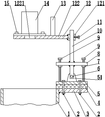
[0007] see figure 1 , the present invention includes a filter cartridge 1, a connecting plate 3, a shock absorbing rubber 4, a base 5, a rotating shaft 6, a positioning plate 8, a sliding rod 10, a sliding seat set screw 11, a sliding seat 12, a take-up post 13, a laser ranging Instrument 14, several base bolts 2, several lock nuts 7, several adjusting screws 9 and several hexagon socket head cap screws 15, the upper surface of the base 5 is welded with ear plates 51, and the sliding seat 12 includes sliding Cover 121 and flat plate 122, the left part of the flat plate 122 is provided with a circular hole 1221, the connecting plate 3 is welded on the right side of the filter cartridge 1, and the damping rubber 4 is clamped on the connecting plate by the base bolt 2 3 and the base 5, the slide bar 10 is connected with the ear plate 51 through the rotating shaft 6, the positioning plate 8 is welded on the slide bar 10, the adjusting screw 9 is mounted on the positioning plate 8,...
PUM
 Abstract
Description
Claims
Application Information