
Miniature thermal conductivity detector being insensitive to flow rate

A thermal conductivity detector, miniature technology, applied in semiconductor/solid-state device parts, light guide, microstructure technology, etc., can solve the difficulty of Wheatstone bridge and related circuit connection, poor stability of supporting film, easy damage, etc. Problems, to achieve good thermal insulation effect, to avoid the effect of heat transfer reduction

Pending Publication Date: 2018-07-24
BEIJING UNIV OF TECH
View PDF0 Cites 4 Cited by
  • Summary
  • Abstract
  • Description
  • Claims
  • Application Information

AI Technical Summary

Problems solved by technology

[0004] 1. In the current design of miniature thermal conductivity detectors, the straight-through structure is almost completely adopted, that is, the gas flows directly through the thermal conductivity cell. Although this design ensures the response speed, it also makes the thermal conductivity detector very sensitive to the flow rate and the flow rate fluctuates. It will have a great adverse effect on its working performance, and due to the direct impact of the airflow on the suspended support membrane in the existing design, the stability of the support membrane will deteriorate and it will be easily damaged
Although there is a diffusion structur

Method used


Image

  • Miniature thermal conductivity detector being insensitive to flow rate
  • Miniature thermal conductivity detector being insensitive to flow rate
  • Miniature thermal conductivity detector being insensitive to flow rate

Examples


Example Embodiment

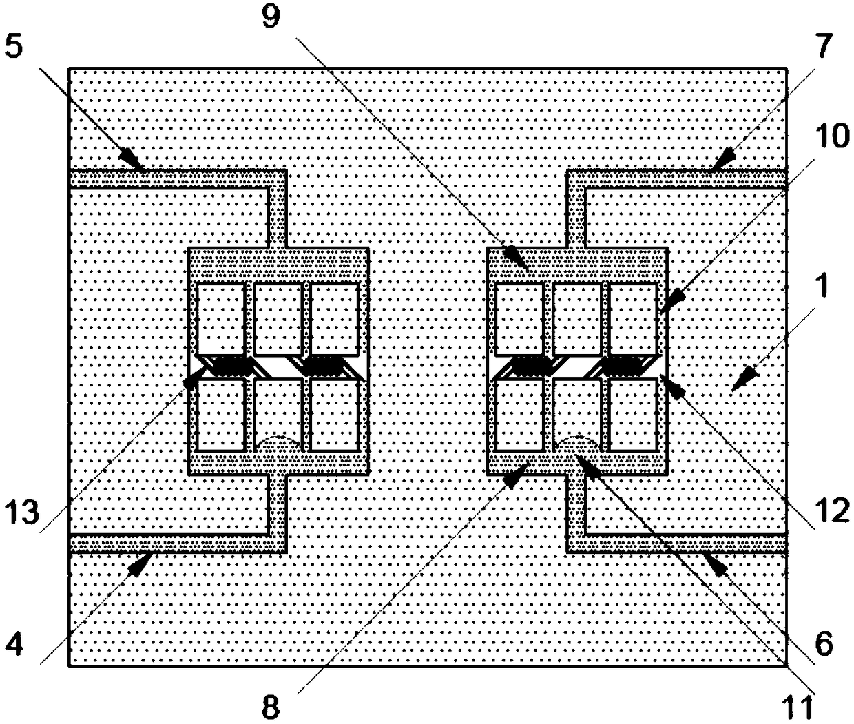
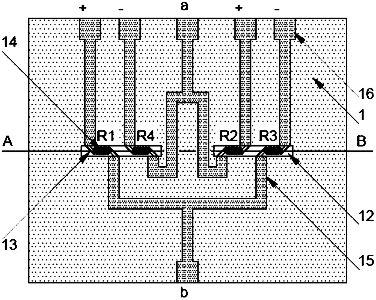
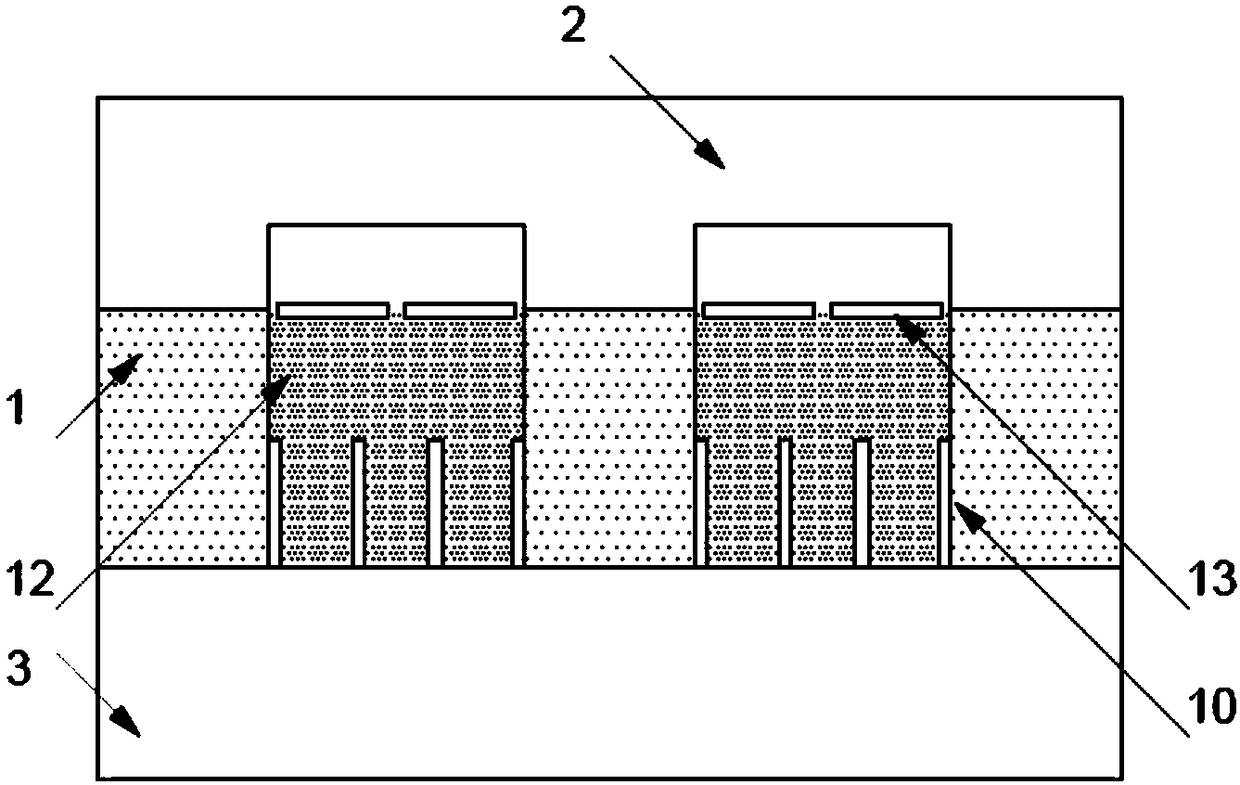
[0035] The present invention provides a miniature thermal conductivity detector that is not sensitive to flow. Its core idea is to process a mesh support film with a thermistor on the front and back of a silicon substrate and a "total score" form of The micro channel realizes its non-coplanar design. At the same time, the micro cuboid thermal conductivity cell penetrates the silicon substrate, and its lower part is connected to the branch channel, which realizes the semi-diffusion design of the air flow channel and the thermal conductivity cell. The overall structure ensures the micro thermal conductivity detection In addition to the requirements for response speed, the influence of gas flow and pressure fluctuations on performance is greatly reduced. At the same time, because there are no microchannels on the front side of the silicon substrate, it is easier to connect the bridge and related circuits on it. The miniature thermal conductivity detector of this design has not bee...


PUM

PropertyMeasurementUnit
Thicknessaaaaaaaaaa
Thicknessaaaaaaaaaa

Abstract

The invention provides a miniature thermal conductivity detector being insensitive to the flow rate, and belongs to the field of micro-electronic machine systems. A micro-channel in a sum-divide-sum type etched on the back face of a silicon substrate serves as an air flow channel, an etching technique is adopted on the front face of the silicon substrate to penetrate through the silicon substrateto form two micro cuboid thermal conduction pools, meanwhile, a net-shaped supporting membrane located on the front face of the silicon substrate and a thermistor on the net-shaped supporting membraneare formed and hung above the thermal conduction pools, and finally the silicon substrate is bonded with a glass cover plate and a glass substratum to complete manufacturing. The structure achieves that the air flow channel and the thermistor are designed in a non-coplanar mode, the semi-diffusion type design of the air flow channel and the thermal conduction pools is achieved by combining the layout of the micro-channel in a branch type, the influence of air flow rate fluctuation on the working performance of the thermal conductivity detector is greatly reduced, and meanwhile, the requirement for response speed is considered. In addition, non-coplanar design avoids interference on circuit integration by a channel in a traditional design, and thus an electrical bridge and a relevant circuit can be easily and practically integrated on the front face of the silicon substrate.

Description

technical field [0001] The invention relates to the field of micro-electromechanical systems, in particular to the design of a miniature thermal conductivity detector which is not sensitive to flow, and can be widely used in the analysis of various mixed gases. Background technique [0002] The thermal conductivity detection method is the earliest method applied to gas detection. This method uses the characteristic that the temperature of the thermistor in the thermal conductivity detector changes with the volume fraction of the gas to be measured, and realizes the detection of different gas volume fractions. detected. The thermal conductivity detector has the advantages of simple device and low price, and because it responds to almost all gases, it is a general-purpose detector, so it is widely used in the field of gas analysis. [0003] Traditional thermal conductivity detectors have many problems such as low detection sensitivity, large error, large volume and heavy weig...

Claims


Application Information

Patent Timeline
IPC IPC(8): G01N25/20B81B7/02
CPCG01N25/20B81B7/02
Inventor 夏国栋贺鑫
Owner BEIJING UNIV OF TECH
Learn More