
Adjusting device for installation angle of multiple probes and measuring and compensating methods

A technology for installing angle and adjusting devices, which is applied to measuring devices, feedback control, instruments, etc. It can solve problems such as poor flexibility of angle adjustment devices or instruments, manufacturing errors of device parts, and errors that cannot be eliminated, so as to shorten the adjustment time , improve the accuracy of the installation angle, and improve the effect of difficult adjustment

Active Publication Date: 2018-07-24
BEIJING UNIV OF TECH
View PDF10 Cites 4 Cited by
  • Summary
  • Abstract
  • Description
  • Claims
  • Application Information

AI Technical Summary

Problems solved by technology

[0005] The invention overcomes the problems of poor adaptability of installation angles of multiple probes and manufacturing errors of device parts in non-contact laser measurement and testing. In the adjustment process, a self-adaptive coarse adjustment and fine adjustment method is proposed. After adopting the measurement method of the present invention, the angle deviation caused by the manufacturing error can be automatically compensated, and the improvement is several times or even several times higher than that of a single measuring head. Ten times the measurement efficiency
[0006] The present invention aims at the defects of the existing traditional angle adjustment method and the manufacturing error of parts, and carries out principle innovation. The basic idea is: 1. The error cannot be eliminated, but it can be compensated as much as possible
In order to meet these two criteria, the traditional angle adjustment device or the poor flexibility and complex structure of the instrument should be broken.

Method used


Image

  • Adjusting device for installation angle of multiple probes and measuring and compensating methods
  • Adjusting device for installation angle of multiple probes and measuring and compensating methods
  • Adjusting device for installation angle of multiple probes and measuring and compensating methods

Examples


Embodiment Construction

[0042] Below in conjunction with accompanying drawing, present embodiment is described further:

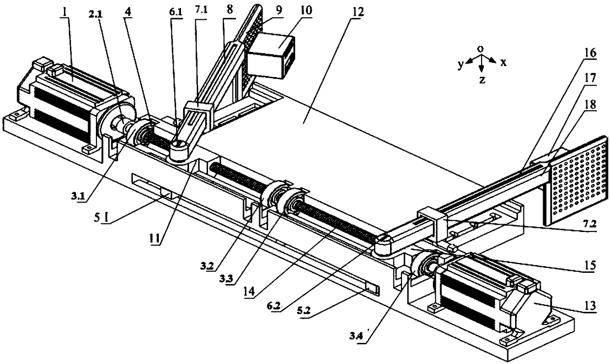
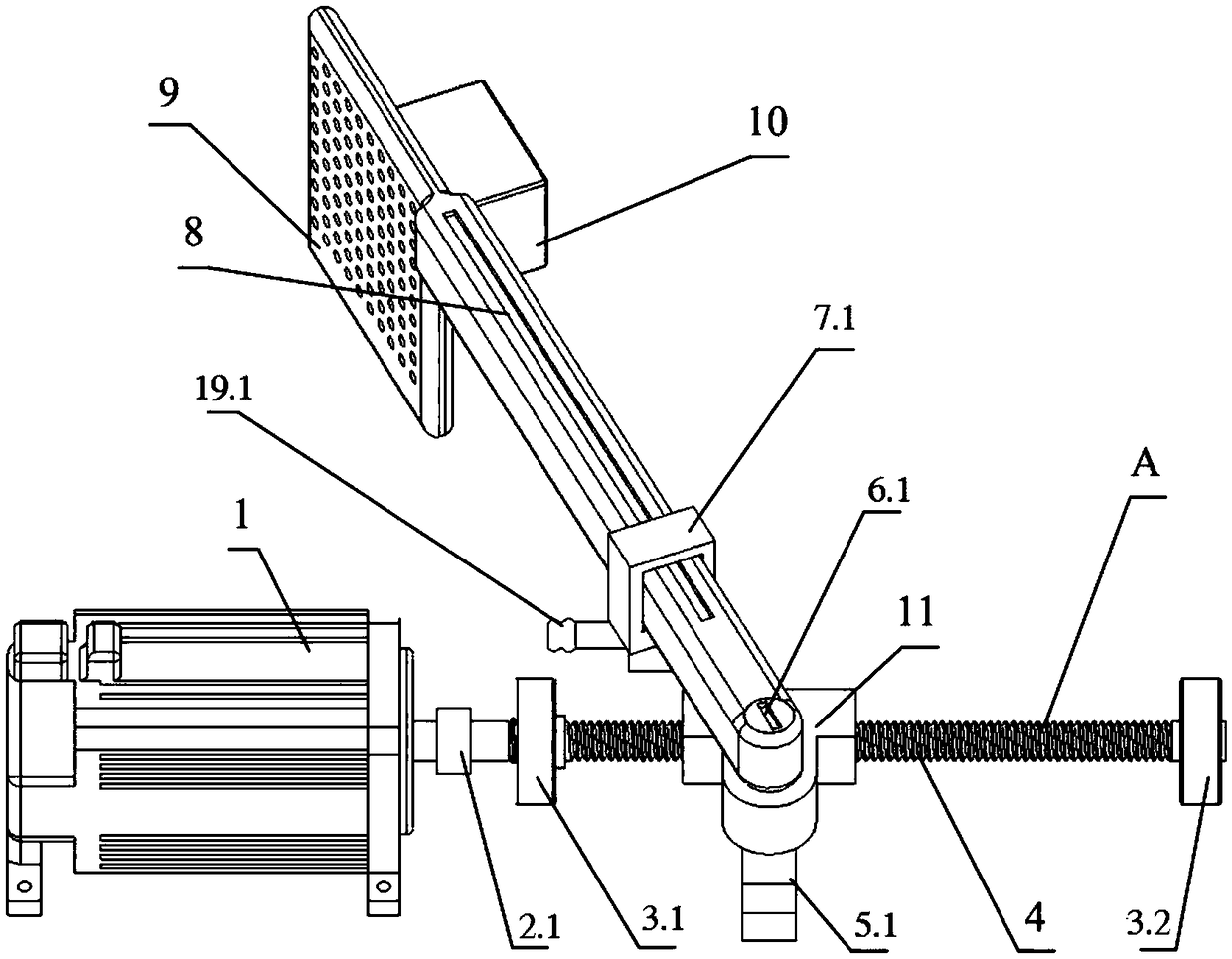
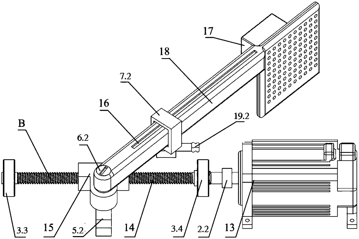
[0043] The working principle of the present invention is as figure 1 As shown, each structural member Figure 2-4 As shown, a multi-probe installation angle adjustment device is composed of a workbench (12), a left adjustment and measurement system (A) and a right adjustment measurement system (B). The left adjustment and measurement system (A) and the right adjustment and measurement system (B) are arranged symmetrically on the workbench (12).

[0044] In the left adjusting and measuring system (A): the left laser measuring head (10) is fixed on the preset hole at one end of the left mounting arm (9) through a refined lock nut, and the axial long grating of the left mounting arm (8) Installed in the axial direction of the upper end of the left mounting arm (9), the other end of the left mounting arm (9) is connected with the left special nut (11) and the horizontal fine-tuning ...


PUM


Abstract

The invention discloses an efficient adjusting device for the installation angle of multiple probes and measuring and compensating methods, which belong to the fields of precision test technologies, instrument technologies and experimental technologies. A measuring device is composed of left and right adjusting and measuring systems. The left and right measuring systems are equipped with two longgratings, are installed coaxially, and operate independently through precision screws. The left and right measuring systems can measure their respective displacements, and then, obtain the accurate installation angle through conversion based on the side-angle relationship. The invention provides a device and a method for specific angle measurement at the same time. The problems of the poor adaptability of the installation angle of multiple probes and the manufacturing error of device components in non-contact laser measurement and test are overcome. As long as the angle parameter values required by left and right probes are input, the installation angle can be adjusted automatically and accurately. Adaptive coarse adjustment and fine adjustment methods are put forward during adjustment. Byadopting the measuring method of the invention, compensation can be made automatically for the angle deviation caused by manufacturing error.

Description

technical field [0001] The invention relates to a device for automatically adjusting the mounting angle of the measuring heads when two non-contact laser measuring heads are used for precise measurement of mechanical parts, and an angle measurement and error compensation method, belonging to the field of precision testing technology, instrument technology and test technology . Background technique [0002] Angle is one of the important parameters in precision testing. Angle is an indispensable basic index in the fields of national defense industry, scientific research and machinery manufacturing. When using non-contact optical measuring instruments to measure parts with complex mechanical surfaces, according to the measurement principle, the laser beam is often projected at a certain angle on the surface to be measured, that is, it is necessary to adjust multiple probe space angle parameters before starting the measurement. It meets the algorithm requirements of the measure...

Claims


Application Information

Patent Timeline
Patent Type & Authority Applications(China)
IPC IPC(8): G05D3/12G01D21/00
CPCG01D21/00G05D3/12
Inventor 石照耀王涛
Owner BEIJING UNIV OF TECH
Learn More