
Product defect detection and location method, device and equipment and computer readable medium

A technology of product defect and positioning method, applied in the field of artificial intelligence, to achieve the effect of standardization and improvement

Inactive Publication Date: 2018-07-24
BEIJING BAIDU NETCOM SCI & TECH CO LTD
View PDF4 Cites 35 Cited by
  • Summary
  • Abstract
  • Description
  • Claims
  • Application Information

AI Technical Summary

Problems solved by technology

[0006] Embodiments of the present invention provide a product defect detection and positioning method, device, equipment and computer-readable medium to solve or alleviate the above technical problems in the prior art

Method used


Image

  • Product defect detection and location method, device and equipment and computer readable medium
  • Product defect detection and location method, device and equipment and computer readable medium
  • Product defect detection and location method, device and equipment and computer readable medium

Examples


Embodiment 1

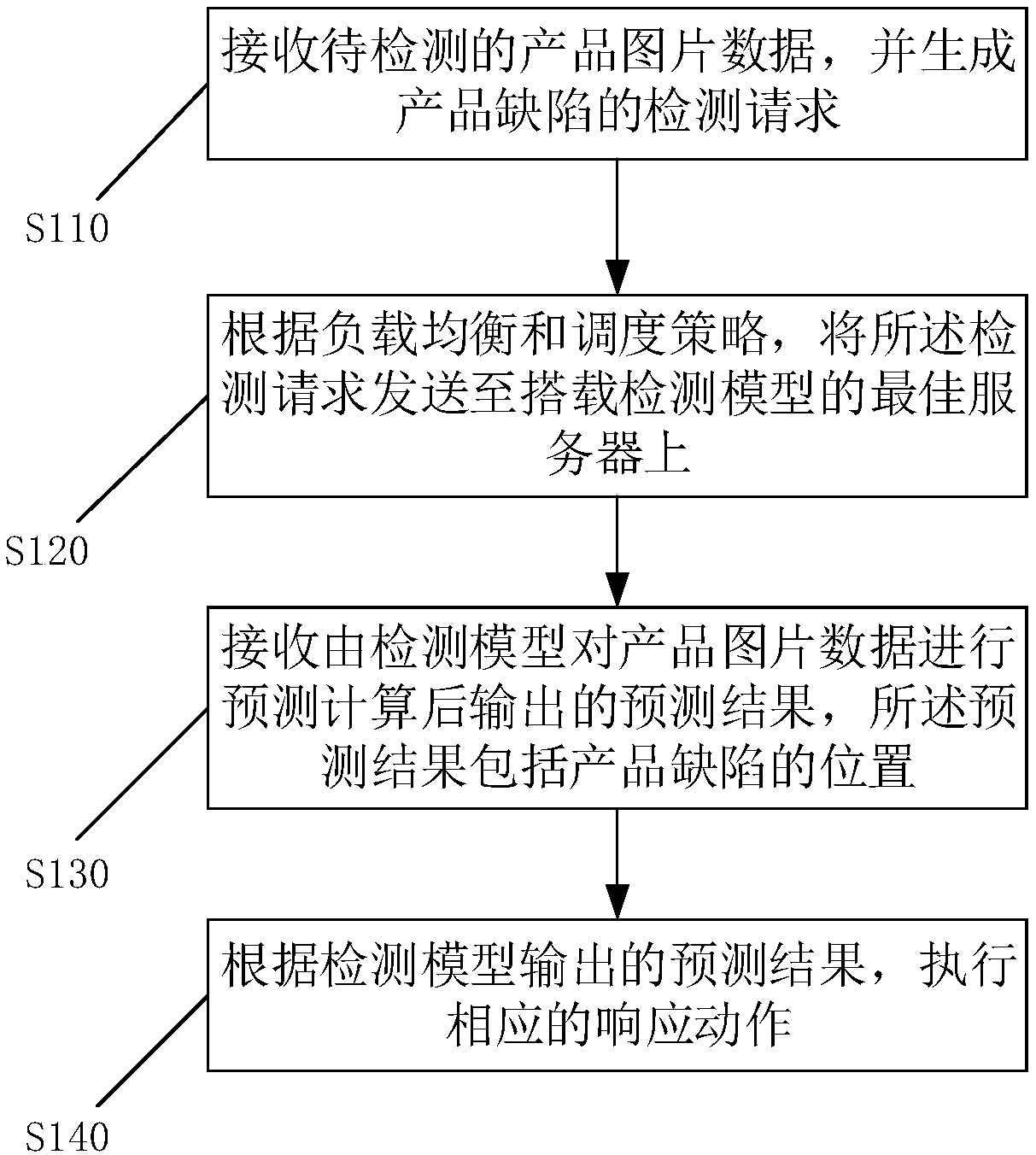
[0067] see figure 1 , which is a flowchart of the steps of the method for detecting and locating product defects in Embodiment 1 of the present invention. Embodiment 1 provides a method for detecting and locating product defects, including the following steps:

[0068] S110: Receive product image data to be detected, and generate a product defect detection request.

[0069] When it is necessary to detect the surface defect of the product, the image of the product surface can be collected first, for example, it can be collected by a camera and other equipment. Then, after the image information of the corresponding product is collected, a detection request is generated to detect surface defects of the product.

[0070] S120: Send the product image data and the detection request to the optimal server equipped with the detection model according to the load balancing and scheduling strategy.

[0071] Before sending the detection request, first monitor the deployment of the detec...

Embodiment 2

[0081] The difference from Embodiment 1 is that this Embodiment 2 also updates the detection model on the basis of Embodiment 1. The specific scheme is as follows:

[0082] see Figure 4 , which is a flow chart of the steps of the method for detecting and locating product defects in the second embodiment. Embodiment 2 provides a method for detecting and locating product defects, including the following steps:

[0083] S210: Receive product image data to be detected, and generate a product defect detection request.

[0084] S220: Send the product picture data and the detection request to the best server equipped with the detection model according to the load balancing and scheduling strategy.

[0085] S230: Receive a prediction result output after the detection model predicts and calculates the product image data, the prediction result includes the position of the product defect.

[0086] S240: Execute a corresponding response action according to the prediction result output...

Embodiment 3

[0091] see Figure 5 , which is a flow chart of the steps of the method for detecting and locating product defects in the third embodiment. Embodiment 3 provides a method for detecting and locating product defects, including the following steps:

[0092] S310: Receive product image data and a detection request for product defects.

[0093] S320: Carry out a prediction calculation of product defect on the image data of the product through the detection model and output a prediction result, the prediction result including the position of the product defect.

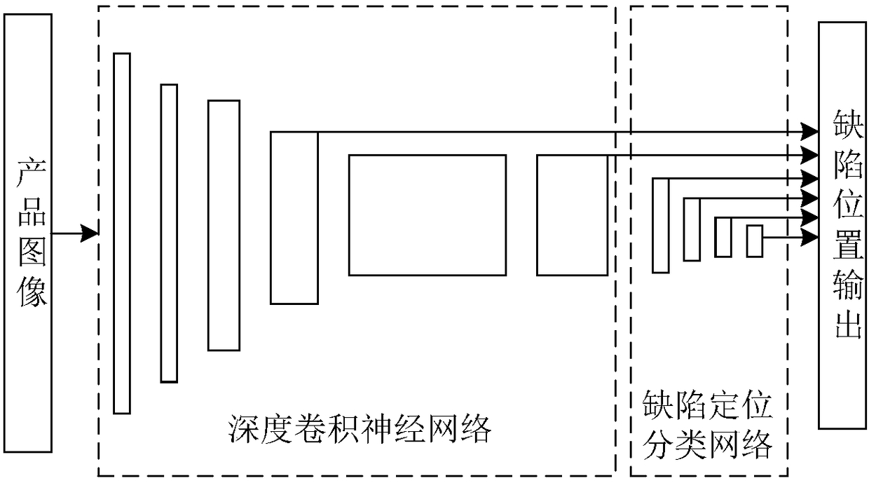
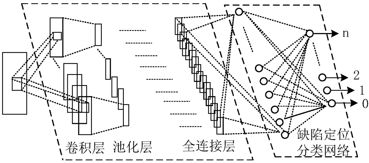
[0094] Wherein, the detection model includes: a deep convolutional neural network and a defect location and classification network.

[0095] The deep convolutional neural network is used to extract features of product images, and the features are input into the defect location and classification network.

[0096] The defect location classification network is used to judge whether there is a defect in the features extract...


PUM


Abstract

The invention provides a product defect detection and location method comprising the following steps that the product image data to be detected are received, and a product defect detection request isgenerated; the product image data and the detection request are transmitted to the optimal server loading the detection model according to the load balancing and scheduling strategy; the prediction result outputted after prediction and calculation of the product image data by the detection module is received, wherein the prediction result includes the product defect position; and the correspondingresponse action is performed according to the prediction result outputted by the detection model. The product image acquired in real time is detected and judged and finally the position of the product defect and the category of the product defect can be acquired. Furthermore, iterative updating of the detection model is performed so that the detection model is enabled to be suitable for the latest requirements of the production environment, and the industrial production line can be significantly enhanced in the aspects of classification accuracy, expandability and standardization.

Description

technical field [0001] The present invention relates to the technical field of artificial intelligence, in particular to a product defect detection and positioning method, device, equipment and computer readable medium. Background technique [0002] In the production scenario of traditional industrial manufacturing, quality inspection is a key link in the production process. In the fields of steel production, automobile manufacturing, paper making, battery manufacturing, solar panel manufacturing, etc., an important means of product quality control is to inspect the surface state of the product to determine whether the product has flaws and defects, and according to the inspection As a result, the product is processed accordingly. In the production of traditional industrial manufacturing, this kind of quality inspection based on the surface state of the product is mostly manual inspection or semi-automatic optical instrument-assisted quality inspection, which is not only in...

Claims


Application Information

Patent Timeline
Patent Type & Authority Applications(China)
IPC IPC(8): G06T7/00G01N21/88
CPCG06T7/0004G01N21/8851G01N2021/8861G01N2021/8887G06T2207/10004G06T2207/20081G06T2207/20084G06T2207/30108
Inventor 冷家冰刘明浩梁阳文亚伟张发恩郭江亮唐进尹世明
Owner BEIJING BAIDU NETCOM SCI & TECH CO LTD
Learn More