Pinhole camera detecting method based on binocular detection

A pinhole camera and binocular technology, applied in image analysis, image data processing, instruments, etc., can solve the problems of high cost, low real-time performance, low recognition accuracy, etc., achieve high cost performance, improve recognition accuracy, cost reduction effect

Inactive Publication Date: 2018-07-24
PLA PEOPLES LIBERATION ARMY OF CHINA STRATEGIC SUPPORT FORCE AEROSPACE ENG UNIV
View PDF4 Cites 11 Cited by
  • Summary
  • Abstract
  • Description
  • Claims
  • Application Information

AI Technical Summary

Problems solved by technology

This method also uses a single detector, which mainly relies on algorithms to improve the recognition ability,

Method used


Image

  • Pinhole camera detecting method based on binocular detection
  • Pinhole camera detecting method based on binocular detection
  • Pinhole camera detecting method based on binocular detection

Examples


Embodiment

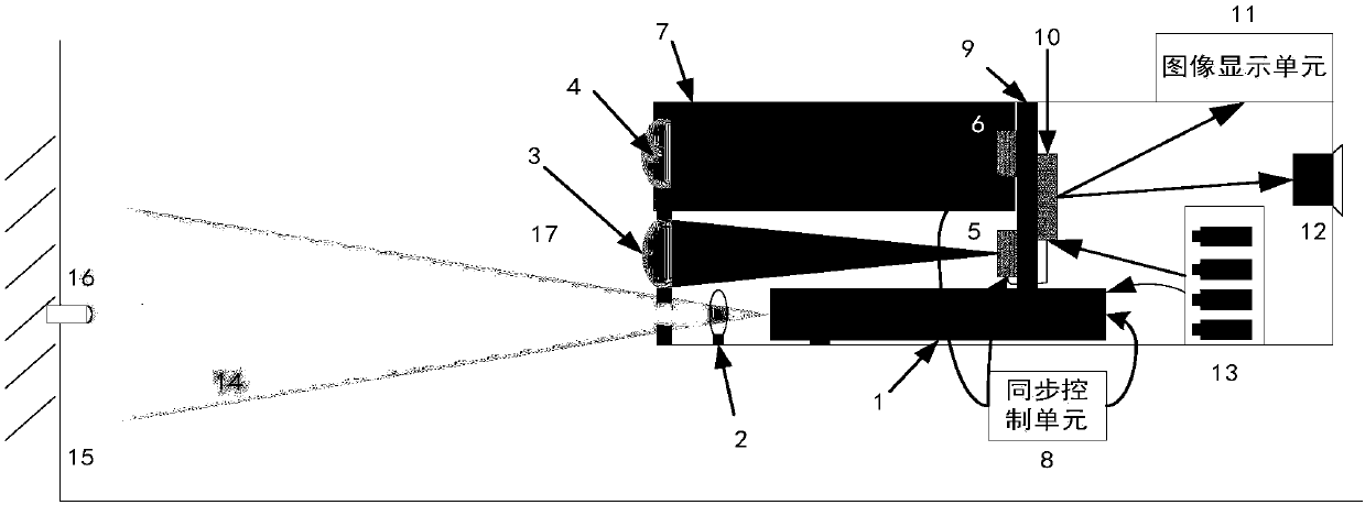
[0034] combined with figure 1The pinhole camera detection device based on binocular detection of the present invention will be further described in detail with examples. The detection device of the present invention includes an 850nm semiconductor continuous invisible laser 1, a transmitting lens 2, a receiving lens 3 and a receiving lens 4, CCD5 and CCD6, a lateral shifter 7, a synchronization control unit 8, an image difference unit 9, and an information processing unit 10 , an image display unit 11, an alarm 12 and a power pack 13. The continuous laser light 14 that laser device 1 sends enlarges divergence angle after expanding by emitting lens 2, then transmits on the suspicious wall surface 15 that may have pinhole camera 16; Lateral shifter 7 controls camera 2 (the second receiving lens 4 and the second CCD6 ) to a suitable lateral distance, the synchronous control unit 8 controls two CCD5 and 6 frame synchronization, and receives the reflected light 17 of the wall 15 a...


PUM

PropertyMeasurementUnit
Wavelengthaaaaaaaaaa

Abstract

The invention discloses a pinhole camera detecting method based on binocular detection, which is characterized in that pinhole cameras hidden in a room can be effectively detect and its accurate position can be determined; based on the feature of the cat-eye effect of the pinhole cameras that the reflected light is returned along the original path and the scattering angle is quite small, and by means of an invisible laser beam, suspicious areas in a room with possible pinhole cameras can be scanned; two CCDs having certain transverse distance are adopted to simultaneously detect the reflectedlight of the suspicious area; the imaging time sequence of two CCDs maintain simultaneous, and after the sequence images of the two CCDS undergo difference and information processing, the difference images with high recognition degree can be obtained, and effective identification can be realized. The invention is advantageous in that as the two images obtained are both active detection images, thedifference between the reflected light at background can be little, and the difference between the reflected light of the pinhole cameras can be great, and thereby without too much subsequent information processing, the images aimed by the pinhole camera with high recognition degree can be obtained; the identifying accuracy can be greatly increased, and false-alarm rate can be reduced.

Description

technical field [0001] The invention belongs to the technical field of photoelectric detection and identification, and in particular relates to a detection method of a pinhole camera based on binocular detection. Background technique [0002] With the rapid development of photoelectric technology, the security monitoring system has been widely used in public security evidence collection, reconnaissance surveillance, facility and road monitoring, etc., which has played a positive role in the stability of the country and society. But at the same time, the emergence and proliferation of pinhole cameras have greatly threatened personal privacy and property safety, and various unhealthy security phenomena such as sneak shots and blackmail have begun to breed in the society. This is because the size of the pinhole camera is very small, and its caliber is generally only on the order of millimeters, so its stealth effect is very good, and it can be installed in imperceptible walls, ...

Claims


Application Information

Patent Timeline
IPC IPC(8): G06T7/30
CPCG06T7/30
Inventor 赵延仲郭惠超梁丹华张来线单聪淼陈剑彪孙华燕李迎春
Owner PLA PEOPLES LIBERATION ARMY OF CHINA STRATEGIC SUPPORT FORCE AEROSPACE ENG UNIV
Why Eureka
Try Eureka