
Explosion-proof positive pressure power distribution cabinet

A power distribution cabinet and electronic technology, applied in substation/power distribution device housing, electrical components, substation/switch layout details, etc., can solve the problem of poor heat dissipation, inability to prevent the entry and accumulation of humid air, wind, sand and dust, electrical failure and Explosion and other problems, to avoid external moisture, realize automatic explosion-proof degassing and decompression and heat dissipation, and improve safety

Active Publication Date: 2018-07-24
CHINA HELON EXPLOSION PROOF ELECTRIC
View PDF9 Cites 12 Cited by
  • Summary
  • Abstract
  • Description
  • Claims
  • Application Information

AI Technical Summary

Problems solved by technology

[0002] Most of the power distribution cabinets used in the market are non-sealed, so the non-sealed power distribution cabinets and chassis cannot prevent the entry and accumulation of humid air, flammable and explosive gases, wind and sand dust, and cause electrical components to be corroded, mildewed and damaged. Oxidation is prone to dangers such as electrical failure and explosion, which seriously shortens the service life of the equipment and becomes a major problem in the use of electrical equipment
In order to prevent the entry of humid air, flammable and explosive gases, and wind and sand dust in the market, sealed power distribution cabinets have also appeared, but the heat dissipation effect is poor. For high-heating instruments, the heat cannot be dissipated, and it is also easy to explode.

Method used


Image

  • Explosion-proof positive pressure power distribution cabinet
  • Explosion-proof positive pressure power distribution cabinet
  • Explosion-proof positive pressure power distribution cabinet

Examples


Embodiment Construction

[0028] The present invention will be specifically introduced below in conjunction with the accompanying drawings and specific embodiments.

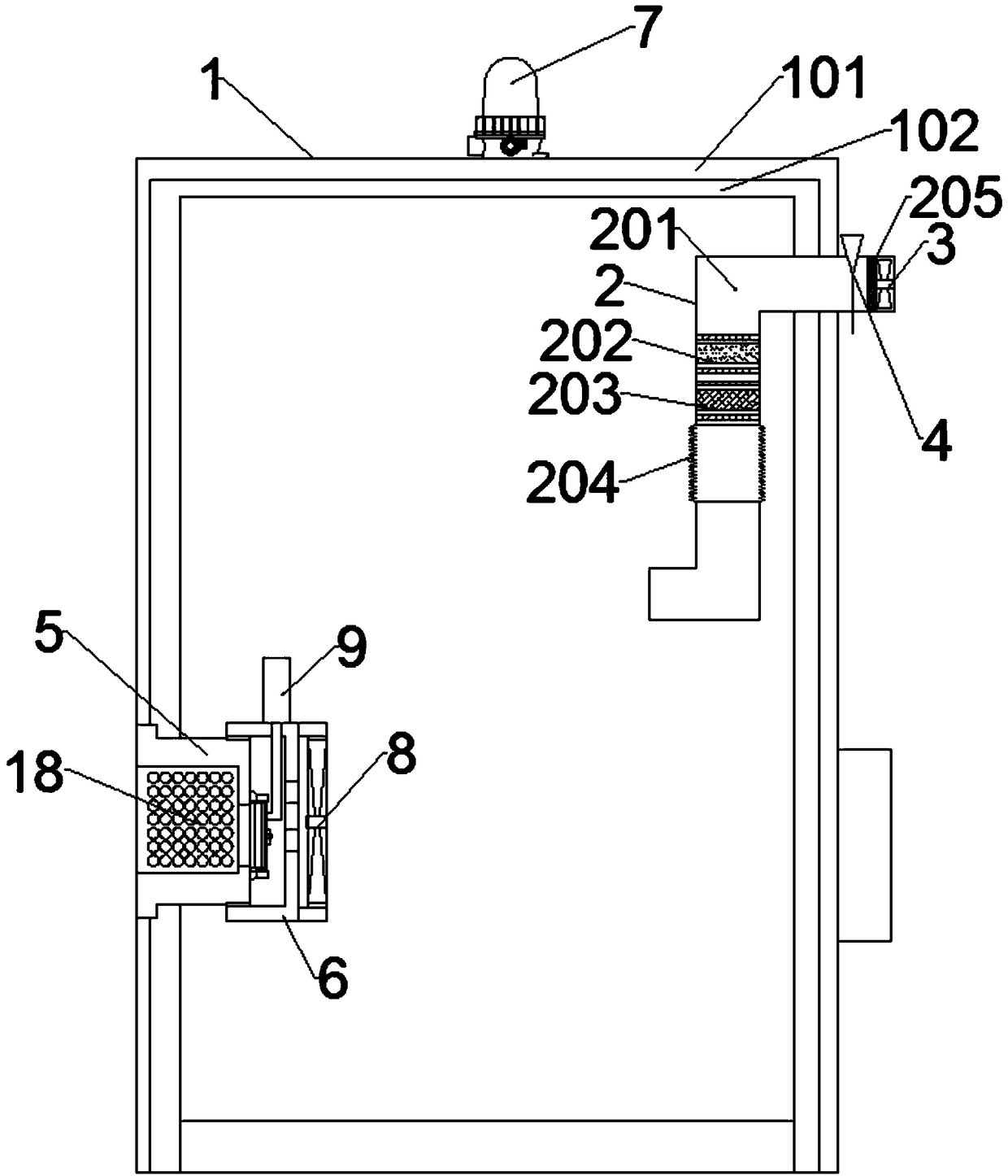
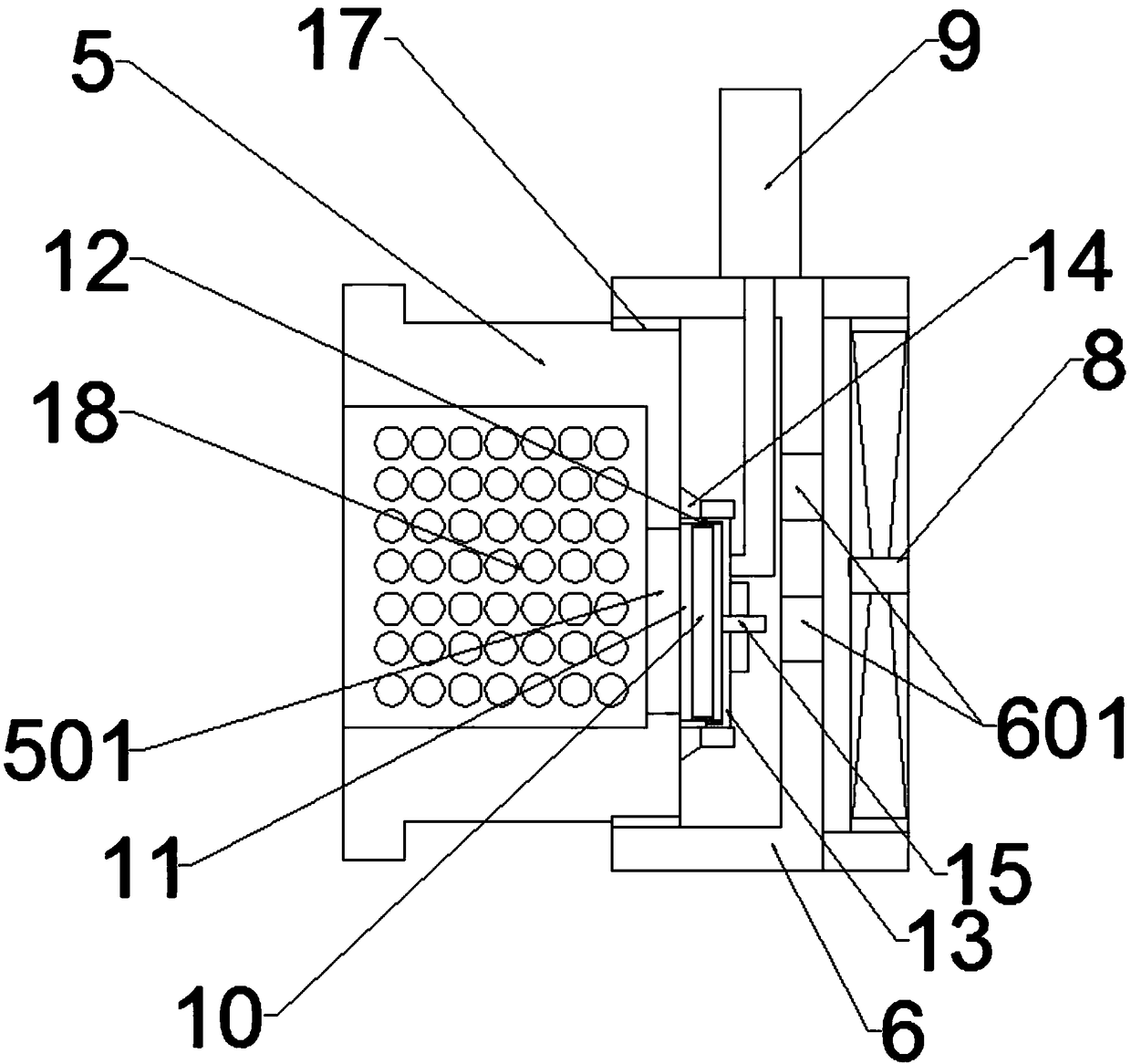
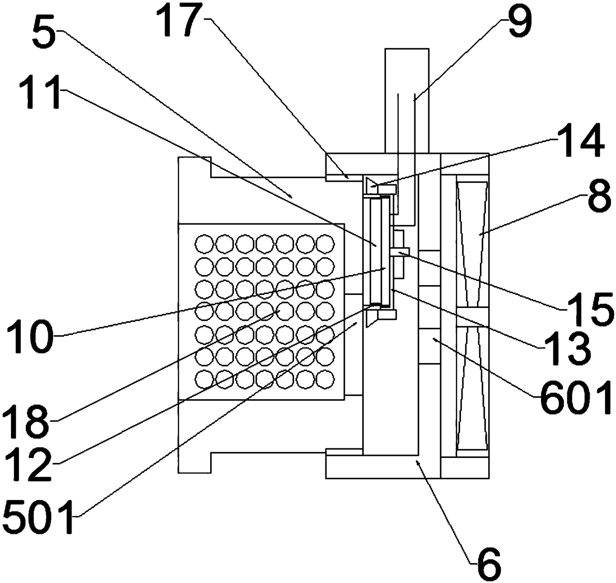
[0029] Explosion-proof positive pressure power distribution cabinet, including: shell 1, the air inlet and air outlet arranged on the outer shell 1, the air inlet pipe 2 assembly arranged at the air inlet, the explosion-proof deflation assembly arranged at the air outlet; the air inlet pipe The assembly consists of: an air intake pipe 2, a first suction fan 3 arranged at the entrance of the air intake pipe 2, and a solenoid valve 4 arranged on the air intake pipe 2; The ventilation box 5 of the through hole 501 corresponds to the position of the first through hole 501 and is provided with the ventilation cover 6 of the second through hole 601, and the second suction fan 8 arranged on the ventilation cover 6 seals the sealing of the first through hole 501. The component controls the opening and closing of the first through hole 501 and is ...


PUM


Abstract

The invention discloses an explosion-proof positive pressure power distribution cabinet. The explosion-proof positive pressure power distribution cabinet comprises: a housing, an air inlet and an airoutlet which are formed in the housing, an air inlet pipe assembly disposed at the air inlet, and an explosion-proof deflation assembly disposed at the air outlet; the air inlet pipe assembly comprises: an air inlet pipe, a first suction fan disposed at an inlet of the air inlet pipe, and an electromagnetic valve disposed on the air inlet pipe; the explosion-proof deflation assembly includes a ventilating box which is fixed on the air outlet and having a first through hole, a ventilating cover which is corresponding to the first through hole and has a second through hole, a second suction fandisposed on the ventilating cover, a sealing assembly for sealing the first through hole, and an electronic telescopic rod for controlling the opening and closing of the first through hole and connected to the sealing assembly. The invention can seal the power distribution cabinet, can prevent external moisture, flammable and explosive gas, and dust from entering the power distribution cabinet, can monitor the pressure and the temperature of the power distribution cabinet in real time, and can automatically realize explosion-proof decompression and heat dissipation; the safety is improved, theautomatic level is improved, and the manpower burden is reduced.

Description

technical field [0001] The invention relates to the field of power distribution cabinets, in particular to an explosion-proof positive pressure power distribution cabinet. Background technique [0002] Most of the power distribution cabinets used in the market are non-sealed, so the non-sealed power distribution cabinets and chassis cannot prevent the entry and accumulation of humid air, flammable and explosive gases, wind and sand dust, and cause electrical components to be corroded, mildewed and damaged. Oxidation is prone to dangers such as electrical failure and explosion, which seriously shortens the service life of the equipment and becomes a major problem in the use of electrical equipment. In order to prevent the entry of humid air, flammable and explosive gases, and wind and sand dust, sealed power distribution cabinets have also appeared in the market, but the heat dissipation effect is poor. For high-heating instruments, the heat cannot be dissipated, and it is al...

Claims


Application Information

Patent Timeline
IPC IPC(8): H02B1/56H02B1/28H02B1/30
CPCH02B1/28H02B1/306H02B1/565
Inventor 张乃月
Owner CHINA HELON EXPLOSION PROOF ELECTRIC
Learn More