Machine tool protective cover with precision maintaining function

A precision maintenance and protective cover technology, applied in the direction of manufacturing tools, maintenance and safety accessories, metal processing machinery parts, etc., can solve the problems of machine tool deformation, machine tool processing accuracy reduction, installation space increase, etc., to achieve the effect of weakening the influence

Inactive Publication Date: 2018-07-27
NINGXIA KOCEL MACHINE TOOL ACCESSORIES
View PDF5 Cites 6 Cited by
  • Summary
  • Abstract
  • Description
  • Claims
  • Application Information

AI Technical Summary

Problems solved by technology

However, if the protective cover is installed on the machine tool after debugging, there will be a problem that the machine tool will be deformed due to the weight of the protective cover, and the processing accuracy of the previously adjusted mobile module will be destroyed, resulting in a reduction in the processing accuracy of the machine tool
As a protective device capable of avoiding this problem, the prior art discloses a protective cover consisting of a rear cover fixed to the rear side of the bottom of the machine tool and a front cover cooperating with the rear cover surrounding the processing area, and the cover There are casters so as to be movable relative to the rear cover, however, in the case where the entire machine tool is installed in a much larger protective cover than the machine tool as described above, the protective cover requires more installation space than the machine tool, thereby Brings the problem of increased installation space
Since the guard is larger than the machine tool, another problem arises that the splashed coolant may flow down the inner surface of the guard and possibly leak out of the machine tool

Method used


Image

  • Machine tool protective cover with precision maintaining function
  • Machine tool protective cover with precision maintaining function
  • Machine tool protective cover with precision maintaining function

Examples


Embodiment Construction

[0027] In order to enable those skilled in the art to better understand the technical solutions of the present invention, the present invention will be further described in detail below in conjunction with specific examples. The embodiments described below are exemplary only for explaining the present invention and should not be construed as limiting the present invention. If no specific technique or condition is indicated in the examples, it shall be carried out according to the technique or condition described in the literature in this field or according to the product specification.

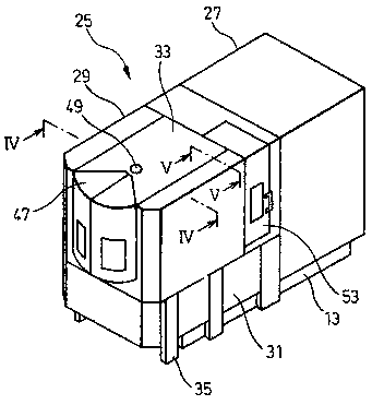
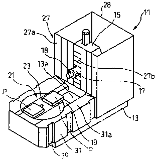
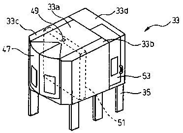
[0028] According to an embodiment of the present invention, figure 1 is an isometric perspective view of the machine tool protective cover of the present invention, figure 2 It is an isometric perspective view of the rear cover and the lower enclosure of the machine tool protective cover of the present invention, image 3 is an isometric perspective view of the front cover of the machine to...


PUM


Abstract

The invention relates to a machine tool protective cover with a precision maintaining function. The machine tool protective cover mainly comprises a front cover shell and a rear cover shell. The frontcover shell comprises lower coaming plates and an upper coaming plate disposed above the lower coaming plates, wherein a plurality of grooves are formed in the outer sides of the lower coaming plates, and supporting bosses are arranged on the inner sides of the lower coaming plates. Adjustable supports embedded in the grooves are arranged at the lower end of the upper coaming plate, and sealing pressing plates are arranged at the lower end of the upper coaming plate. By arranging elastic sealing elements on the supporting bosses, the upper coaming plate is embedded inside the lower coaming plates. The rear cover shell mainly comprises first guide rail protective covers which move in the horizontal direction in a telescopic mode and second guide rail protective covers which move in the vertical direction in a telescopic mode, a spindle head of a machine tool moves, and the first guide rail protective covers and the second guide rail protective covers act as sealing partition plates between a machine tool processing area and a machine tool stand column. The machine tool protective cover with the precision maintaining function reduces the deformation affecting the machine tool without increasing the installation space of the machine tool, allows the machine tool to maintain own inherent machining precision, and does not need to repeatedly perform machine tool debugging.

Description

technical field [0001] The invention belongs to the technical field of machine tool protection, in particular to a machine tool protective cover with the function of maintaining precision, which is suitable for precision machine tools performing high-precision machining operations. Background technique [0002] As an important functional part of CNC machine tools, machine tool protective covers have the functions of safety protection, precision maintenance and environmental protection, and are more and more valued by machine tool manufacturers and machine tool users. Taking the horizontal machining center with an exchange table as an example, in order to prevent the chips and coolant from splashing out of the machine tool when the machine tool is processing the workpiece, the usual practice is to surround the processing area of ​​the machine tool with a machine tool shield. This machine tool protection The shroud is usually located on the upper part of the machine bed, and i...

Claims


Application Information

Patent Timeline
IPC IPC(8): B23Q11/08
CPCB23Q11/0833
Inventor 武申龙兰浩南徐静
Owner NINGXIA KOCEL MACHINE TOOL ACCESSORIES
Why Eureka
Try Eureka