Gear grinding device

A gear and shaft grinding technology, which is applied in the direction of grinding/polishing safety devices, grinding machines, grinding slides, etc., can solve the problems of small application range and inability to meet the needs of gear inner hole grinding, and achieve the effect of wide application range

Active Publication Date: 2019-11-05
重庆台华传动技术有限公司
View PDF7 Cites 1 Cited by
  • Summary
  • Abstract
  • Description
  • Claims
  • Application Information

AI Technical Summary

Problems solved by technology

[0004] The present invention intends to provide a gear grinding device to solve the problem that the traditional grinding device cannot meet the needs of grinding the inner holes of gears with different apertures and has a small application range

Method used


Image

  • Gear grinding device
  • Gear grinding device

Examples


Embodiment Construction

[0018] The present invention will be described in further detail below by means of specific embodiments:

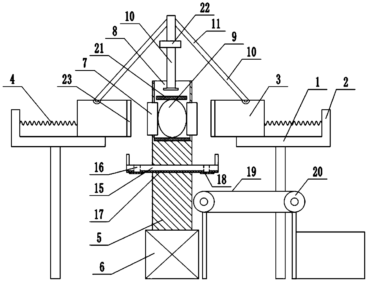
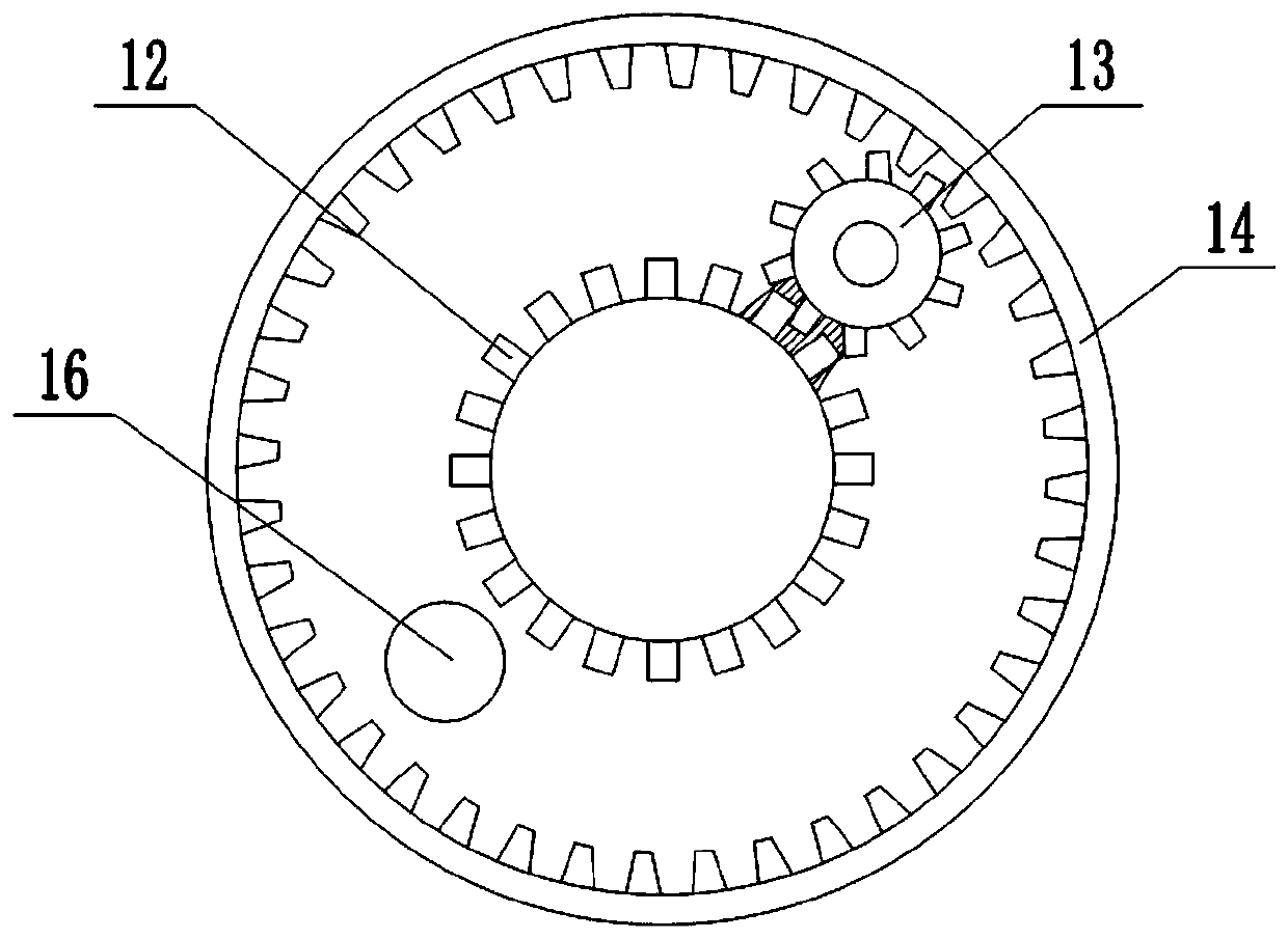
[0019] The reference signs in the accompanying drawings of the description include: support table 1, vertical plate 2, clamping block 3, support spring 4, grinding shaft 5, first motor 6, grinding teeth 7, cavity 8, air bag 9, lower pressure rod 10. Connecting rod 11, driving gear 12, planetary gear 13, gear frame 14, collecting plate 15, drop opening 16, first magnet 17, baffle plate 18, conveyor belt 19, transmission wheel 20, support plate 21, fixed ring 22, rodent23.

[0020] The embodiment is basically as figure 1 Shown: The gear grinding device includes a frame and a clamping mechanism. The frame is provided with two facing support platforms 1, and the support platform 1 is provided with a vertical plate 2 and a chute. The clamping mechanism includes two facing The clamping blocks 3 are set, and the opposite sides of the two clamping blocks 3 are provided with tee...


PUM


Abstract

The invention relates to a gear polishing device. The gear polishing device comprises a rack, support tables are arranged on the rack, clamping blocks are glidingly connected with the support tables,and support springs are arranged between the clamping blocks and the support tables; the gear polishing device also comprises a polishing shaft, polishing teeth are glidingly connected onto the polishing shaft, a cavity is formed in the polishing shaft, an air bag is arranged in the cavity, a downward press rod glidingly connected onto the rack is arranged above the air bag, connecting rods are hinged to two sides of the downward press rod respectively, and the other ends of the connecting rods are hinged to the clamping blocks; a collecting plate is arranged on the polishing shaft, a first magnet is arranged at the bottom of the collecting plate, a falling port is formed in the collecting plate, a baffle is rotationally connected at the falling port, a second magnet is arranged on the baffle, and magnet poles of opposite sides of the first magnet and the second magnet are opposite; a conveying belt and a conveying wheel are arranged below the collecting plate, a third magnet is arranged on the conveying belt, magnet poles of opposite sides of the third magnet and the second magnet are opposite, and the magnetic force of the third magnet is larger than that of the first magnet. Thedevice solves the problem of small application range of traditional polishing devices.

Description

technical field [0001] The invention relates to the field of machining, in particular to a gear grinding device. Background technique [0002] Gear is one of the common parts in mechanical production and is often used as power transmission. The application of gears in transmission appeared very early. At the end of the 19th century, the principle of generative gear cutting method and special machine tools and tools for gear cutting using this principle appeared one after another. With the development of production, the stability of gear operation has been paid more attention. The basic structure of gears includes: gear teeth, tooth grooves, end faces, legal faces, addendum circles, dedendum circles, base circles, and index circles. [0003] Existing gears are often used for power transmission, and holes are often arranged inside them. However, during the processing of the inner holes of the gears, due to the limited machining accuracy, after the inner holes are processed, t...

Claims


Application Information

Patent Timeline
Patent Type & Authority Patents(China)
IPC IPC(8): B24B5/48B24B55/06B24B55/00B24B41/02B24B41/06B24B41/00
CPCB24B5/48B24B41/005B24B41/02B24B41/06B24B55/00B24B55/06
Inventor 刘泽辉
Owner 重庆台华传动技术有限公司
Why Eureka
Try Eureka