Air inlet structure at top part of shot blasting cleaning machine

A shot blasting machine and air inlet technology, which is applied to used abrasive treatment devices, abrasives, metal processing equipment, etc., can solve problems such as unfavorable use, inconvenience to change the blowing direction of the air inlet, and inconvenience to remove dust in the cleaning room. , to achieve the effect of reducing dust, improving shot blasting effect and high practical performance

Active Publication Date: 2018-07-27
江苏龙发铸造除锈设备有限公司
View PDF6 Cites 3 Cited by
  • Summary
  • Abstract
  • Description
  • Claims
  • Application Information

AI Technical Summary

Problems solved by technology

[0003] But the above-mentioned design still has deficiencies, the above-mentioned design is inconvenient to change the blowing direction of the air inlet, it is not easy to remove the dust in the cleaning room, and it is not conducive to people's use. Therefore, we have proposed the air inlet structure on the top of the shot blasting machine to solve the above question

Method used


Image

  • Air inlet structure at top part of shot blasting cleaning machine
  • Air inlet structure at top part of shot blasting cleaning machine
  • Air inlet structure at top part of shot blasting cleaning machine

Examples


Embodiment

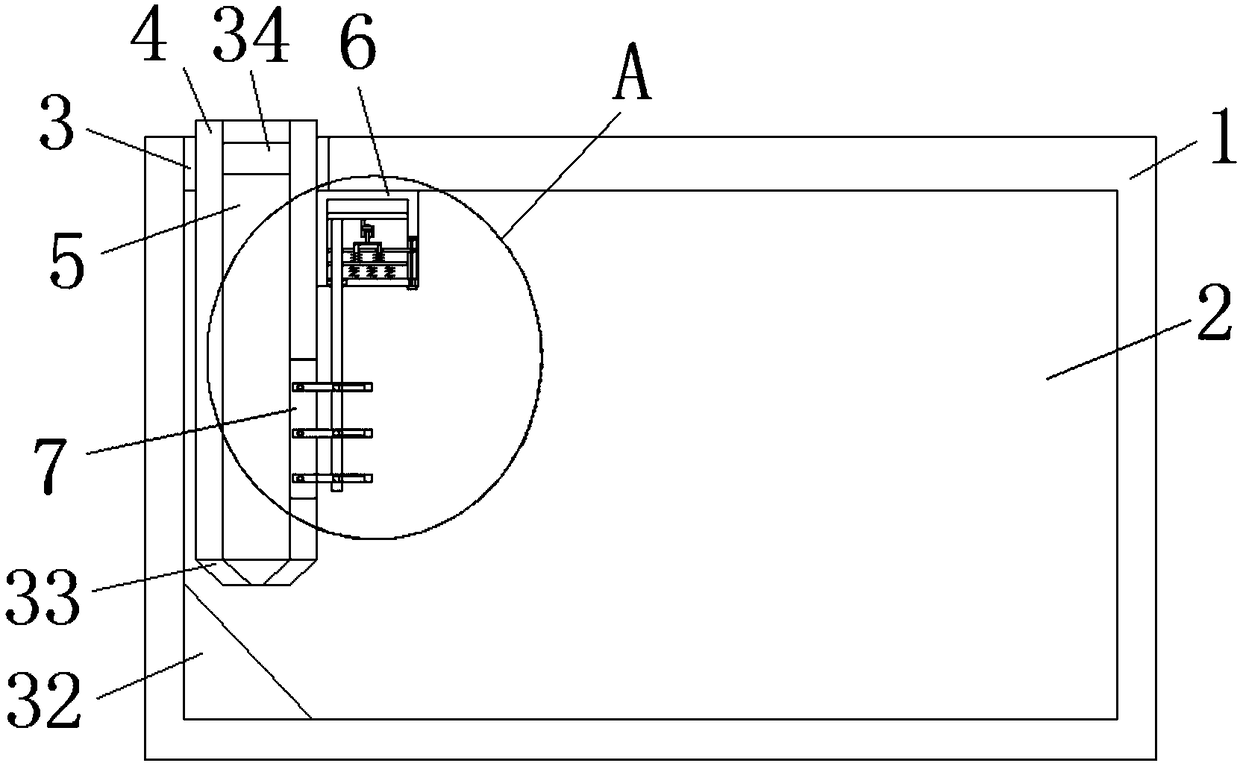
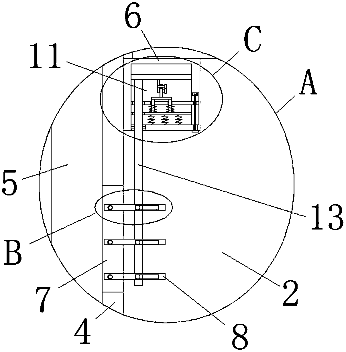
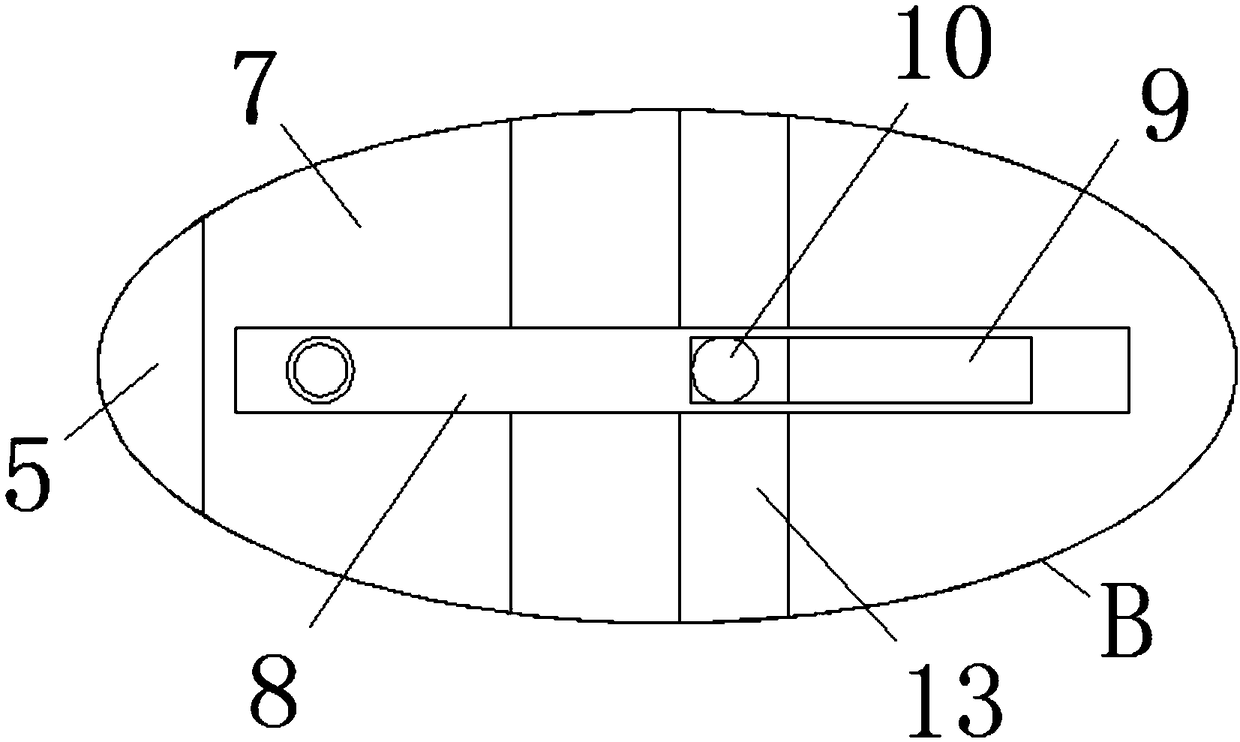
[0028] refer to Figure 1-6, the air inlet structure at the top of the shot blasting machine is proposed in this embodiment, including a cleaning chamber 1, a cavity 2 is provided on the cleaning chamber 1, and a mounting hole 3 is provided on the top inner wall of the cavity 2, and the mounting hole 3 is fixedly installed There is a rectangular air inlet pipe 4, and the rectangular air inlet pipe 4 is provided with an air inlet hole 5, and one side of the rectangular air inlet pipe 4 is fixedly installed with an installation box 6, and the top of the installation box 6 is welded to the top of the cavity 2, and the One side inner wall of the air hole 5 is provided with an air outlet hole 7, and a plurality of baffle plates 8 are rotatably installed in the air outlet hole 7, and the plurality of baffle plates 8 are all located in the cavity 2, and one side of the baffle plate 8 is provided with a sliding A positioning shaft 10 is slidably installed in the hole 9 and the sliding...


PUM


Abstract

The invention discloses an air inlet structure at the top part of a shot blasting cleaning machine, wherein the air inlet structure includes a cleaning room; a cavity is arranged on the cleaning room,an installation hole is formed in the inner wall of the top part of the cavity; a rectangular air intake pipe is fixed in the installation hole, an air intake hole is formed in the rectangular air intake pipe, and an installation box is fixed at one side of the rectangular air intake pipe; the top part of the installation box is welded with the top part of the cavity; an inner wall of one side ofthe air intake hole is provided with an air outlet hole, a plurality of baffle plates are arranged in the air outlet hole in a rotating manner and are all located in the cavity; one side of each baffle plate is provided with a sliding hole; the sliding hole is internally slidingly provided with a positioning shaft; the installation box is provided with an installation cavity; the installation cavity is internally slidingly provided with a sliding plate; one side of the bottom of the sliding plate is fixedly provided with a traction rod. The air intake structure has the advantages of simple structure, high practical performance, easy adjustment of a blowing angle of the air outlet hole, can protect a stepping motor in a buffering manner, reduces dust in the cavity, improves the shot blasting effect and is beneficial for people to use.

Description

technical field [0001] The invention relates to the technical field of shot blasting machines, in particular to a top air inlet structure of the shot blasting machine. Background technique [0002] Shot blasting machine is a common equipment used for surface hardening and surface treatment of parts in casting, metallurgy, machining and other industries. There are no air inlets on both sides of the top of the existing shot blasting machine, and there will be a lot of air on the workpiece. The dust is not clean enough, which affects the shot blasting effect and working environment. After retrieval, the patent document with the application publication number CN102371552A discloses the air inlet structure on both sides of the top of the shot blasting cleaning machine. This design includes: cleaning room, which is set in the cleaning room There are two rows of air inlets on the top of the side of the cleaning room, and an air duct is set in the cleaning room. The air duct is encl...

Claims


Application Information

Patent Timeline
Patent Type & Authority Applications(China)
IPC IPC(8): B24C9/00
CPCB24C9/00
Inventor 罗厚镇
Owner 江苏龙发铸造除锈设备有限公司
Why Eureka
Try Eureka