
Conveniently mounted and detached creel for warp knitting machine

A warp knitting machine and creel technology, which is applied in warp knitting, textiles, papermaking, knitting, etc. It can solve the problems of falling, troublesome loading and unloading process of the yarn bobbin limit rod, and yarn bobbin limit, etc., to achieve loading and unloading The effect of convenient process, avoiding falling, and strong adaptability

Active Publication Date: 2018-07-27
浙江金研新材料科技有限公司
View PDF11 Cites 1 Cited by
  • Summary
  • Abstract
  • Description
  • Claims
  • Application Information

AI Technical Summary

Problems solved by technology

The working principle of the warping machine is that after the yarn is drawn out from the bobbin on the creel, it passes through the guide rod, the rear reed, the guide rod, the photoelectric end stopper, the split reed, the fixed width reed, the length measuring roller and the guide roller. Winding on the drum one by one, all the warp yarns on the drum exit counterclockwise with the rotation of the weaving shaft when reversing the shaft, and then roll onto the weaving shaft, the creel can plan and organize the yarns, but In the process of using the current creel, the yarn bobbin limit lever is very troublesome in the loading and unloading process, and the yarn bobbin is not limited, and it is easy to fall

Method used


Image

  • Conveniently mounted and detached creel for warp knitting machine
  • Conveniently mounted and detached creel for warp knitting machine
  • Conveniently mounted and detached creel for warp knitting machine

Examples


Embodiment Construction

[0025] The implementation of the present application will be described in detail below with reference to the accompanying drawings and examples, so as to fully understand and implement the implementation process of how the present application uses technical means to solve technical problems and achieve technical effects.

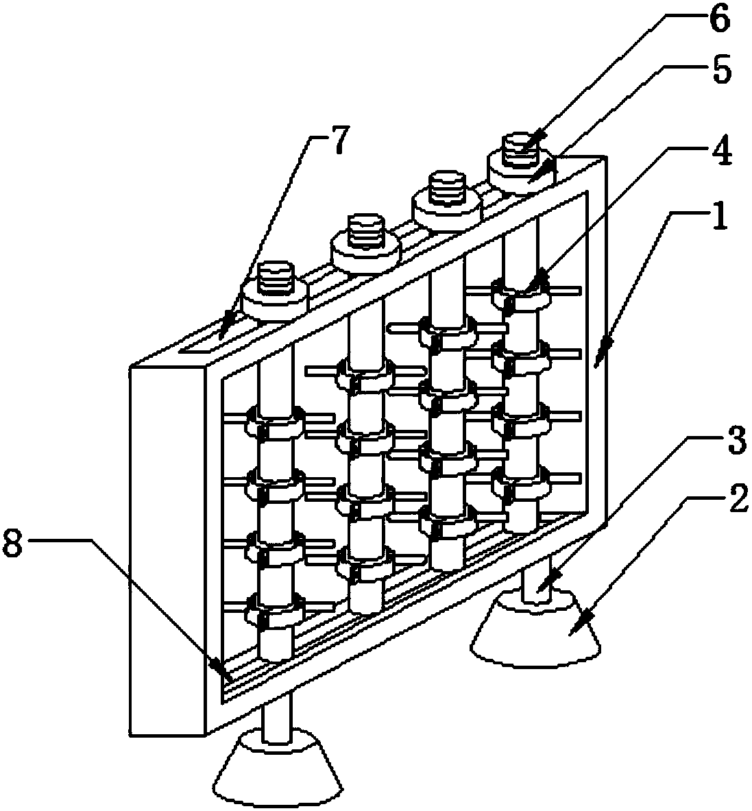
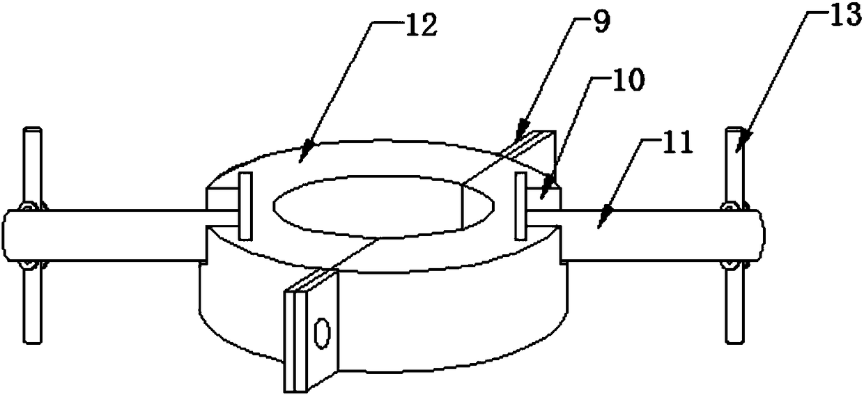
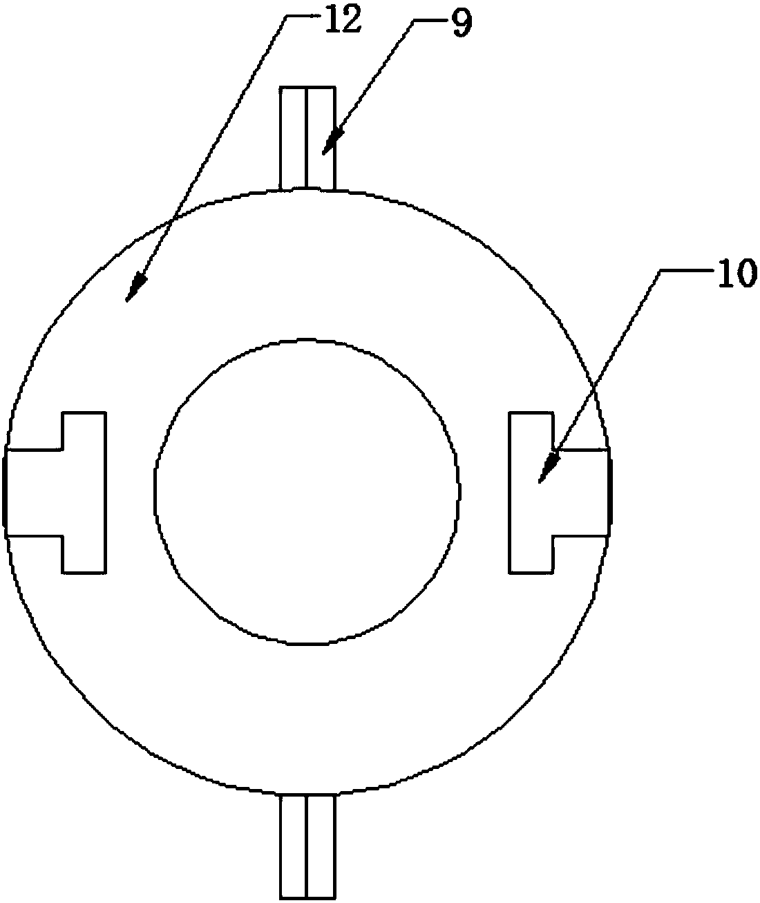
[0026] like Figure 1-6 As shown, a creel for warp knitting machines that is easy to load and unload in the present invention includes: a frame body 1, a chute 8 is provided inside the bottom end of the frame body 1, and the chute 8 is slidably connected with one end of four support rods 6. The other ends of the support rods 6 are interspersed and connected through the slots 7 provided at the top of the frame body 1, and the outer walls of the four support rods 6 are provided with a number of connecting mechanisms 4, and both sides of the bottom end of the frame body 1 are connected by hydraulic rods 3 The hydraulic presses 16 are fixedly connected, and the ...


PUM


Abstract

The invention discloses a conveniently mounted and detached creel for a warp knitting machine. The conveniently mounted and detached creel for the warp knitting machine comprises a frame, wherein a sliding slot is formed in the bottom end of the frame; the sliding slot is connected with one ends of four supporting rods in a sliding manner; the other ends of the four supporting rods are inserted into a through slot formed in the top end of the frame; a plurality of connecting mechanisms are arranged on the outer walls of the four supporting rods. According to the scheme, through the arrangementof the connecting mechanisms, C-shaped rings and T-shaped slots, limiting rods are fixedly mounted, and through attraction between magnets and magnetic cross rods, the limiting rods are fixed, so that operation is simple and mounting and detaching processes are convenient; through arrangement of fixing rods, yarn bobbins are limited, so that the yarn bobbins are prevented from dropping out in theusing process; through torsional springs, the fixing rods are reset, so that in the mounting and detaching processes of the yarn bobbins, the yarn bobbins are not blocked; through arrangement of hydraulic machines, the height of the frame is adjusted, so that adaptability of the creel to different environments and different users is improved and the adaptability is strong.

Description

technical field [0001] The application belongs to the technical field of textiles, and in particular relates to a creel for a warp knitting machine which is convenient for loading and unloading. Background technique [0002] When using a warp knitting machine, one or several groups of yarns arranged in parallel are formed into loops at the same time on all the working needles fed into the machine in the warp direction to form a knitted fabric. This method is called warp knitting, and the fabric is called a warp knitted fabric. , the main loop-forming parts of the warp knitting machine are knitting needles, yarn guide needles, sinkers and pressure plates (for crochet machines). The knitting needles are installed on the needle bed in a row and move with the needle bed. The combs are formed on the board. The warp thread passes through the eyelet of the guide needle, moves with the bar and wraps around the needle, and is woven into a fabric through the mutual cooperation of kni...

Claims


Application Information

Patent Timeline
Patent Type & Authority Applications(China)
IPC IPC(8): D04B27/10
CPCD04B27/10
Inventor 沈泽华
Owner 浙江金研新材料科技有限公司
Learn More