Lubrication system oil way structure of vertical type high speed case

A technology of lubrication system and high-speed box, which is applied in the direction of gear lubrication/cooling, transmission box, and components with teeth. The effect of improving the lubrication effect and the reliability of the work

Active Publication Date: 2018-07-27
HANGZHOU ADVANCE GEARBOX GRP
View PDF8 Cites 5 Cited by
  • Summary
  • Abstract
  • Description
  • Claims
  • Application Information

AI Technical Summary

Problems solved by technology

[0002] At present, the gears and sliding bearings in the high-speed box need to be lubricated forcibly. Usually, the lubricating oil passes through multiple lubricating steel pipes from the oil pump or oil distributor, and then lubricates the bearings and gears at the corresponding position, especially the gearbox lubrication of the upper and lower sub-boxes. The oil circuit is to install the oil distributor inside the box of the lower box, pass through multiple lubricating steel pipes, and then to the upper bearing seat of the high and low speed shaft, and lubricate the sliding bearing through the oil circuit, while the vertical high speed gearbox is front and rear. The low-speed shaft is on the bottom and the high-speed shaft is on the top. There is no way to install an oil distributor and arrange oil pipes inside the box like a horizontal shaft gearbox. Therefore, it is difficult for the oil circuit structure of the lubrication system of a vertical high-speed box

Method used


Image

  • Lubrication system oil way structure of vertical type high speed case
  • Lubrication system oil way structure of vertical type high speed case
  • Lubrication system oil way structure of vertical type high speed case

Examples


Embodiment Construction

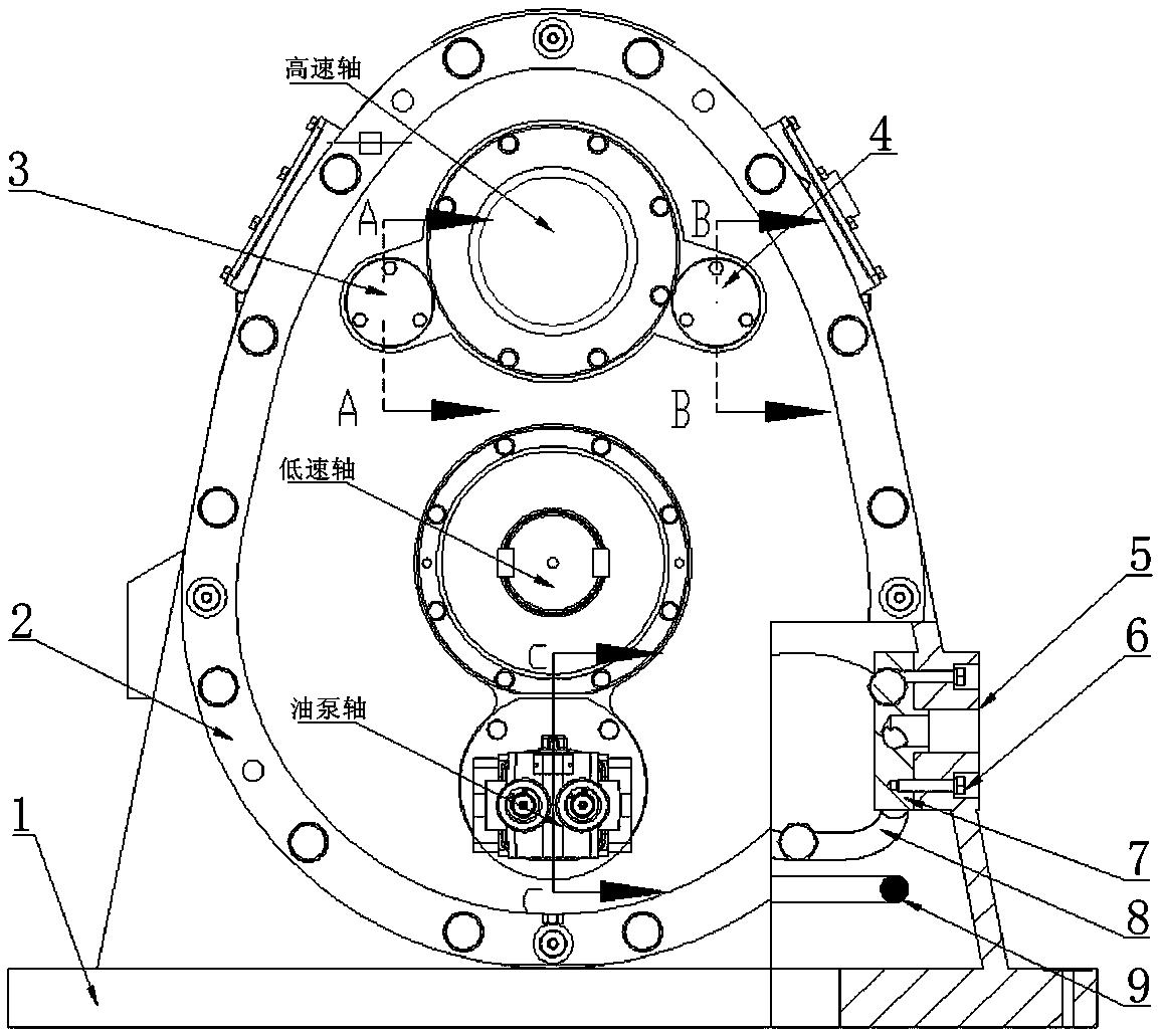
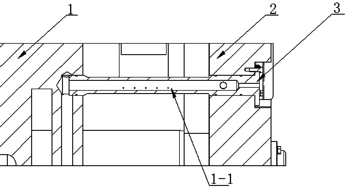
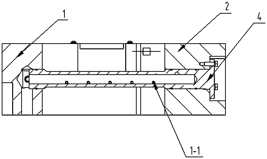
[0018] The present invention will be described in detail below in conjunction with accompanying drawing: Figure 1-6 As shown, the lubricating system oil circuit structure of a vertical high-speed box according to the present invention mainly includes a box body 1, a box cover 2, an oil injection pipe, an oil inlet 5, a bolt 6, an oil distributor 7, a steel pipe, Plug 10 and pipe joint 11, the box body 1 is connected with the box cover 2 to form a front and rear sub-box structure of the gearbox with the high-speed bearing seat hole on the top and the low-speed bearing seat on the bottom; the fuel injection pipe is fixed on the box by bolts. The oil distributor 7 is installed inside the box through bolts 6 and connected to the oil inlet 5. The steel pipe and pipe joint 11 connect the oil distributor 7 with the inside of the box. The oil passage is connected.

[0019] As shown in the figure, the fuel injection pipe includes a first fuel injection pipe 3 and a second fuel inject...


PUM


Abstract

The invention relates to a lubrication system oil way structure of a vertical type high speed case. The lubrication system oil way structure is mainly composed of a case body, a case cover, oil injection pipes, an oil inlet, bolts, an oil distributor, a steel tube, a plug and a tube connector; the case body and the case cover are connected to form a gear case front-and-back separating case structure with a high speed bearing block hole in the upper portion and a low speed bearing block hole in the lower portion, the oil injection pipes are fixed to the case cover through the bolts and are located on the case body and the case cover at the same time, the oil distributor is installed inside the case body through the bolt and communicates with the oil inlet, and the oil distributor and an oilway inside the case body are communicated through the steel tube and the tube connector; the oil injection pipes comprise a first oil injection pipe and a second oil injection pipe, and the first oilinjection pipe and the second oil injection pipe are each provided with a plurality of oil injection small holes used for lubricating and cooling gears for meshing; and an oil return cavity is arranged on the lower face of a low speed bearing block, communicates with an oil injection hole of an oil pump shaft component, and is used for lubricating an oil pumping component. The lubrication systemoil way structure solves the problem about layout of the lubrication system oil way of the vertical type high speed gear case.

Description

technical field [0001] The invention relates to an oil passage structure of a lubrication system of a vertical high-speed gearbox, belonging to the technical field of gearbox hydraulic lubrication. Background technique [0002] At present, the gears and sliding bearings in the high-speed box need to be lubricated forcibly. Usually, the lubricating oil passes through multiple lubricating steel pipes from the oil pump or oil distributor, and then lubricates the bearings and gears at the corresponding position, especially the gearbox lubrication of the upper and lower sub-boxes. The oil circuit is to install the oil distributor inside the box of the lower box, pass through multiple lubricating steel pipes, and then to the upper bearing seat of the high and low speed shaft, and lubricate the sliding bearing through the oil circuit, while the vertical high speed gearbox is front and rear. The low-speed shaft is on the bottom and the high-speed shaft is on the top. There is no way...

Claims


Application Information

Patent Timeline
Patent Type & Authority Applications(China)
IPC IPC(8): F16H57/04F16H57/02F16H57/021
CPCF16H57/02F16H57/021F16H57/0412F16H57/0423F16H57/0424F16H57/0471
Inventor 董龙梅李兴亚王庆良张圣陈方明
Owner HANGZHOU ADVANCE GEARBOX GRP
Why Eureka
Try Eureka