Eureka AIR delivers breakthrough ideas for toughest innovation challenges, trusted by R&D personnel around the world.

Spiral-plate-type heat exchanger with central heat-transfer strengthening effect

A technology of spiral heat exchange and heat transfer enhancement, which is applied to the types of heat exchangers, heat exchanger shells, indirect heat exchangers, etc., and can solve problems such as low flow velocity, low heat exchange efficiency, and small heat transfer film coefficient , to achieve the effect of improving the ability to withstand external pressure, increasing the anti-fatigue ability and prolonging the service life

Inactive Publication Date: 2018-07-27
SUZHOU CITY JINXIANG PRESSURE CONTAINER MFG CO LTD
View PDF0 Cites 1 Cited by
  • Summary
  • Abstract
  • Description
  • Claims
  • Application Information

AI Technical Summary

Problems solved by technology

However, because the flow velocity of this part of the material is very low, the heat transfer film coefficient is very small, so the heat exchange efficiency is very low.
The result of this is the central heat exchange plate and the inner heat exchange plate, the heat exchange plate in this part cannot effectively play the role of heat exchange, reducing the effective heat exchange area of ​​the heat exchanger (while the existing spiral plate heat exchanger And the industry standard of the spiral plate heat exchanger takes this part of the area as the effective heat exchange area of ​​the spiral plate heat exchanger in the calculation)
Such a result may cause the spiral plate heat exchanger to fail to meet the process requirements during actual operation.

Method used


Image

  • Spiral-plate-type heat exchanger with central heat-transfer strengthening effect
  • Spiral-plate-type heat exchanger with central heat-transfer strengthening effect
  • Spiral-plate-type heat exchanger with central heat-transfer strengthening effect

Examples


Embodiment Construction

[0015] The technical solutions of the present invention will be further described below in conjunction with the accompanying drawings and embodiments.

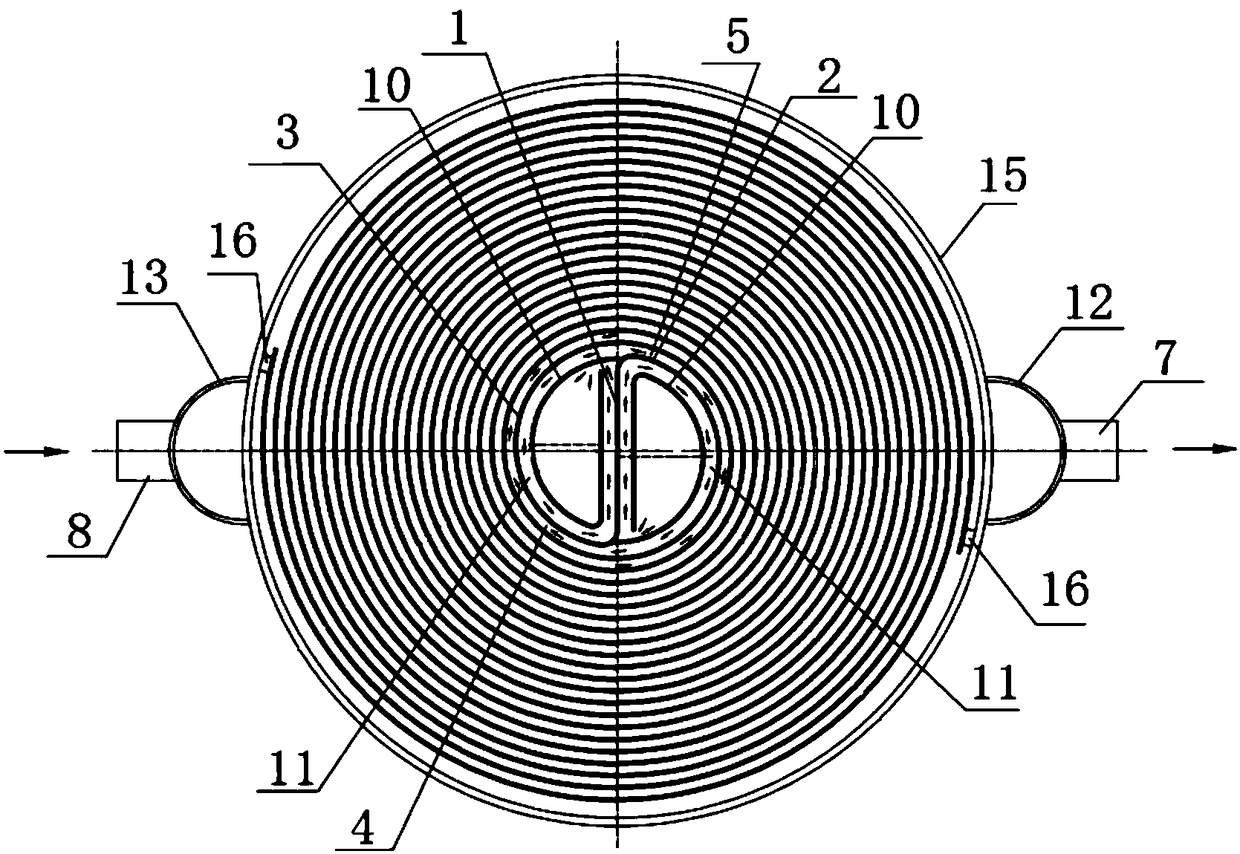
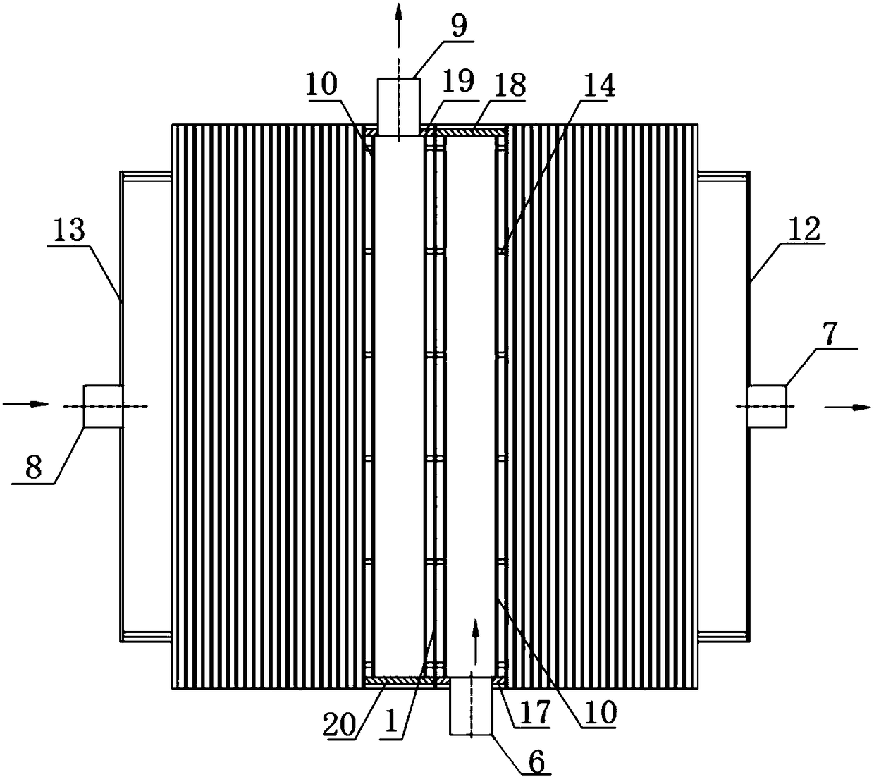
[0016] Such as figure 2 and image 3 The spiral plate heat exchanger with enhanced heat transfer in the center includes a central heat exchange plate 1, and the two sides of the central heat exchange plate 1 are respectively connected with the first spiral heat exchange plate 2 and the second spiral heat exchange plate 3 , the first spiral heat exchange plate 2 and the second spiral heat exchange plate 3 extend spirally and alternately toward the outer circle, forming a first spiral flow channel 4 for the first medium and a second spiral flow channel for the second medium The spiral flow channel 5, the ends and sides of the first spiral flow channel 4 and the second spiral flow channel 5 are independently sealed, and a circular cylinder 15 is sleeved on the outer circle of the spiral heat exchange plate, The cylinder body i...


PUM


Abstract

The invention discloses a spiral-plate-type heat exchanger with a central heat-transfer strengthening effect. The spiral-plate-type heat exchanger comprises a central heat-exchange plate. The two sideedges of the central heat-exchange plate are connected with a first spiral heat-exchange plate piece and a second spiral heat-exchange plate piece correspondingly; flow-guiding cylinders are arrangedat the spiral centers of the first spiral heat-exchange plate piece and the second spiral heat-exchange plate piece and are each of a cylindrical structure with the open side edge, and one side edgesof the open sides of the flow-guiding cylinders are connected with the central heat-exchange plate; and the other positions of the cylinder walls of the flow-guiding cylinders are spaced with all ofthe central heat-exchange plate, the first spiral heat-exchange plate piece and the second spiral heat-exchange plate piece to form central heat-exchange channels correspondingly. The spiral-plate-type heat exchanger has the advantages that firstly, the flow-guiding cylinders are additionally arranged so that media on the two sides of the central heat-exchange plate and the plate pieces on the innermost circles of spiral heat-exchange plates can reach the required flow velocity, the contact area of heat exchange of the media is increased, and the heat-transfer strengthening effect is achieved;and secondly, the flow-guiding cylinders and supporting rings serve as a whole to jointly bear the pressure of the media in the two channels, accordingly, the capability of the spiral-plate-type heatexchanger for bearing the external pressure is improved, and the overall anti-fatigue capability of the spiral-plate-type heat exchanger is improved.

Description

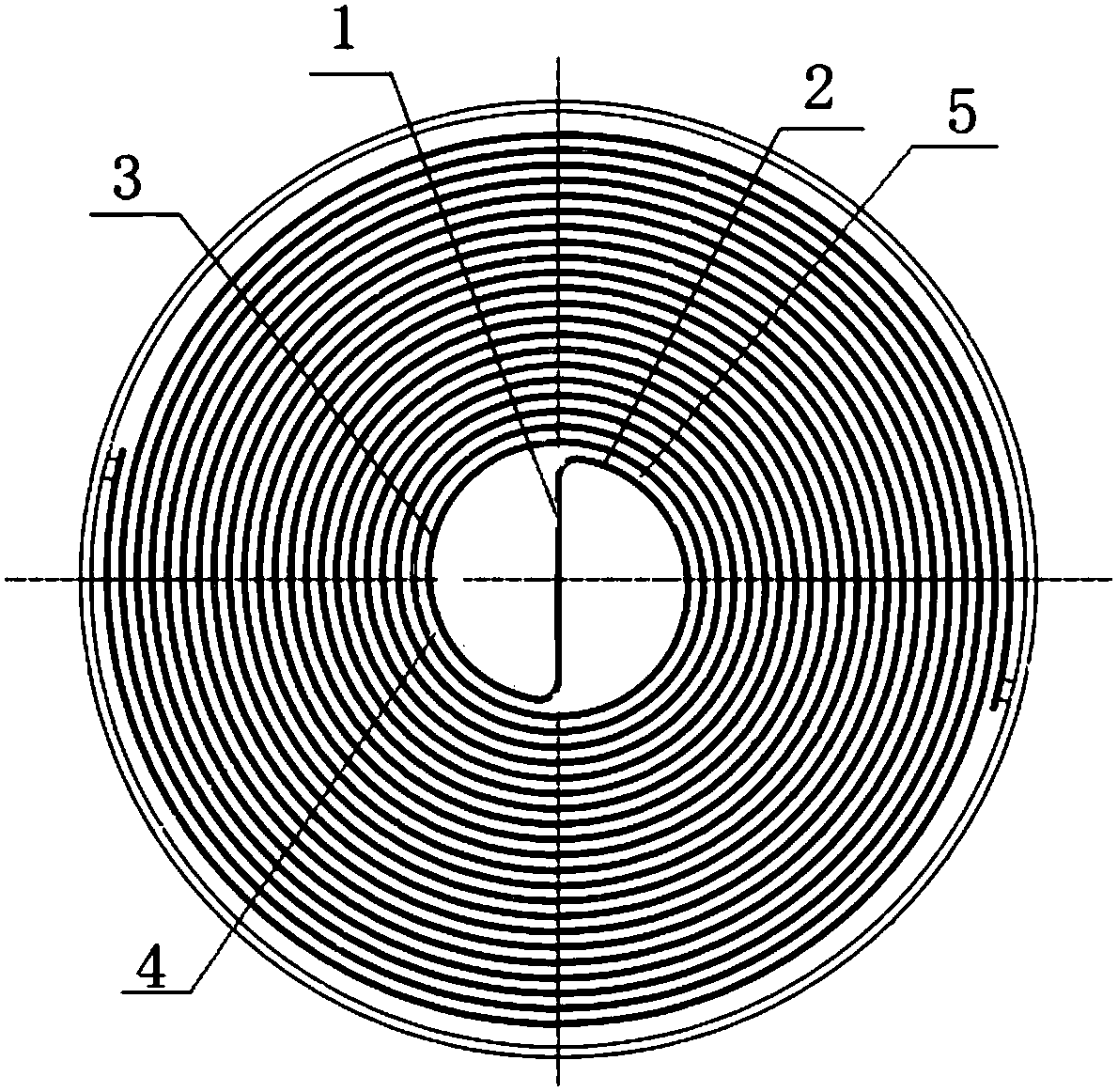
technical field [0001] The invention relates to a spiral heat exchanger, in particular to a spiral plate heat exchanger with center enhanced heat transfer. Background technique [0002] Such as figure 1 For the existing spiral plate heat exchanger shown, due to the limitations of the manufacturing equipment and the structure of the spiral plate heat exchanger itself, the diameter of the central circle varies from 200mm to 500mm according to the area of ​​the spiral plate heat exchanger. In this way, when the material enters the central circle of the heat exchanger (equivalent to two semi-cylinders with a certain radius and height), the material will slowly accumulate and the flow speed will be greatly reduced. The result is that after entering the central semicircle, the material can only exchange heat with the material in the contact part of the inner heat exchange plate (the innermost circle of the spiral heat exchange plate) and the central heat exchange plate. However,...

Claims


Application Information

Patent Timeline
IPC IPC(8): F28D9/04F28F9/007F28F13/06
CPCF28D9/04F28F9/007F28F13/06
Inventor 王晓元周家泉
Owner SUZHOU CITY JINXIANG PRESSURE CONTAINER MFG CO LTD
Why Eureka
Eureka Blog
Learn More