Supercharge Your Innovation With Domain-Expert AI Agents!

High-efficiency and high-temperature ventilation and heat exchange device

A heat exchange device, high temperature technology, applied in heat exchange equipment, lighting and heating equipment, laminated components, etc., can solve the problems of low strength of ventilation heat exchange plate, waste of ventilation pipe material, poor cooling effect, etc., and achieve heat insulation Good effect, shorter cooling time, faster cooling effect

Inactive Publication Date: 2018-07-27
张跃
View PDF10 Cites 0 Cited by
  • Summary
  • Abstract
  • Description
  • Claims
  • Application Information

AI Technical Summary

Problems solved by technology

For example, multiple air ducts are opened in the ventilation heat exchange plate, and the air enters from one end of the air duct, and the air is discharged from the other air duct. However, this structure will make the air duct connect to a long ventilation pipe, which greatly wastes the material of the ventilation pipe. And the cooling speed is slow, the cooling effect is poor
In addition, the existing ventilation and heat exchange plates have low strength and cannot be used in high-burning and pressure-bearing occasions, and their versatility is poor

Method used


Image

  • High-efficiency and high-temperature ventilation and heat exchange device
  • High-efficiency and high-temperature ventilation and heat exchange device
  • High-efficiency and high-temperature ventilation and heat exchange device

Examples


Embodiment 1

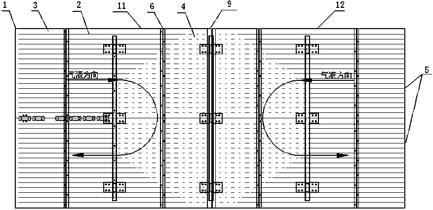
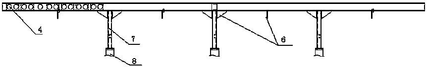
[0038] like figure 1 and figure 2 Shown: a high-efficiency high-temperature ventilation and heat exchange device, including a ventilation heat exchange plate 1, the ventilation heat exchange plate 1 is a hollow plate, and the middle part of the ventilation heat exchange plate 1 is provided with a longitudinally arranged partition plate 9 with gaps, and the ventilation heat exchange plate 1 The hot plate 1 is divided into two parts, the first independent plate body 11 and the second plate body 12. A plurality of partition ribs 2 are arranged in the cavities of the first plate body 11 and the second plate body 12, and the cavity is divided into multiple parts. There are three air ducts 3, and a plurality of ventilation holes 4 are provided on each partition rib 2 near the side of the partition plate 9, so that the gas flow direction in the first plate body 11 and the second plate body 12 is distributed in a U-shaped path.

[0039] Specifically, the ventilated heat exchange pla...

Embodiment 2

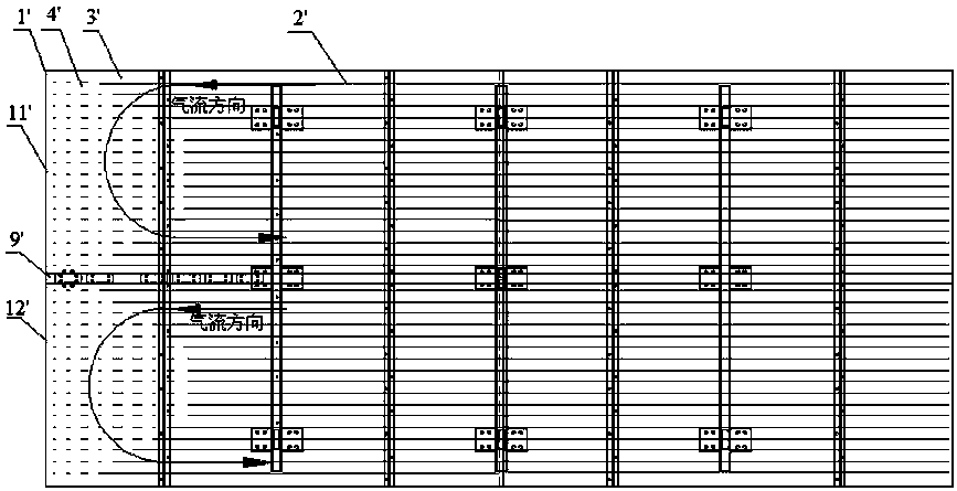
[0047] like image 3 As shown: the difference from Example 1 is: a high-efficiency high-temperature ventilation heat exchange device, including a ventilation heat exchange plate 1', the ventilation heat exchange plate 1' is a hollow plate, and the middle part of the ventilation heat exchange plate 1' is provided with a horizontal The partition plate 9' with a gap divides the ventilation heat exchange plate 1' into two parts: the first plate body 11' and the second plate body 12', and the space between the first plate body 11' and the second plate body 12' A plurality of partition ribs 2' parallel to the partition plate 9' are provided in the cavity, and the cavity is divided into a plurality of air ducts 3'. The left ends of the first plate body 11' and the second plate body 12' are closed, and each The left side of the strip dividing rib 2' is provided with a plurality of ventilation holes 4', nitrogen enters from the right end of the first plate body 11' or the second plate ...

Embodiment 3

[0052] like Figure 4 Shown: the difference with embodiment 2 is that: the left end of the first plate body 11 " is closed, and the left side of each partition rib in the first plate body 11 " is provided with a plurality of ventilation holes 4 ", and the nitrogen gas flows from the first plate body The right end of the body 11" enters, and the setting of the ventilation hole 4" makes the gas flow in the first plate body 11" distributed in a U-shaped path.

[0053] The right end of the second plate body 12 "is closed, and the right side of each partition rib in the second plate body 12" is provided with a plurality of ventilation holes 4", nitrogen enters from the left end of the second plate body 12", and the ventilation holes 4" The setting makes the gas flow in the second plate body 12" distributed in a U-shaped path.

[0054] That is, the air flow directions of the first plate body 11 ″ and the second plate body 12 ″ are opposite.

[0055] Other structures are with embod...


PUM


Abstract

The invention discloses a high-efficiency and high-temperature ventilation and heat exchange device. The high-efficiency and high-temperature ventilation and heat exchange device comprises a ventilation and heat exchange plate. The ventilation and heat exchange plate is a hollow plate. A separating plate with a gap is arranged in the ventilation and heat exchange plate and divides the ventilationand heat exchange plate into a first independent plate body and a second independent plate body. A plurality of separating ribs are arranged in a cavity of the first plate body and a cavity of the second plate body and divide the cavities into a plurality of air channels. A plurality of ventilation holes are formed in each separating rib located at one end of the first plate body and one end of the second plate body so that the flow direction of air flow in the first plate body and the second plate body can be distributed in a U-shaped path mode. The high-efficiency and high-temperature ventilation and heat exchange device has the advantages that the cooling time can be greatly shortened, the cooling effect can be improved, the temperature is more uniform, and thermal expansion is little under the condition that the size of the ventilation and heat exchange plate is equal to that of an existing ventilation and heat exchange plate. The high-efficiency and high-temperature ventilation and heat exchange device has the advantages that the size of the ventilation and heat exchange plate can be a half that of the existing ventilation and heat exchange plate, and the raw material is greatly saved under the condition that the cooling effect of the ventilation and heat exchange plate is same to the cooling effect of the existing ventilation and heat exchange plate. When the high-efficiency and high-temperature ventilation and heat exchange device is used for cooling, the first plate body and the second plate body independently work. When high-efficiency high-temperature ventilationand heat exchange device is used for bearing combustion and pressure, the first plate body and the second plate body work together, and the strength of the overall structure is improved.

Description

technical field [0001] The invention relates to the technical field of ventilation and heat exchange, in particular to a high-efficiency high-temperature ventilation and heat exchange device. Background technique [0002] The current ventilated heat exchange plate is usually cooled externally, but external cooling will greatly reduce the cooling speed and the cooling effect is poor. The internal cooling structure of the ventilated heat exchange plate has also appeared in the prior art. For example, multiple air ducts are opened in the ventilation heat exchange plate, and the air enters from one end of the air duct, and the air is discharged from the other air duct. However, this structure will make the air duct connect to a long ventilation pipe, which greatly wastes the material of the ventilation pipe. And the cooling speed is slow, and the cooling effect is poor. In addition, the existing ventilated heat exchange plates have low strength and cannot be used in high-burni...

Claims


Application Information

Patent Timeline
IPC IPC(8): F28F3/12
CPCF28F3/12
Inventor 张跃
Owner 张跃
Features
  • R&D
  • Intellectual Property
  • Life Sciences
  • Materials
  • Tech Scout
  • Unparalleled Data Quality
  • Higher Quality Content
  • 60% Fewer Hallucinations
Learn More