Eureka AIR delivers breakthrough ideas for toughest innovation challenges, trusted by R&D personnel around the world.

Arcing detection method based on fusion of ultraviolet images, infrared images and optical images

An optical image and detection method technology, which is applied in the direction of using optical methods for testing and testing dielectric strength, etc., can solve problems such as time-consuming, expensive, and ineffective results, and achieve low-cost and safe detection effects

Active Publication Date: 2018-07-27
南京视道信息技术有限公司
View PDF8 Cites 9 Cited by
  • Summary
  • Abstract
  • Description
  • Claims
  • Application Information

AI Technical Summary

Problems solved by technology

[0003] The first is the inspection method of the inspection vehicle. This method cannot achieve real-time inspection, and the inspection must be carried out after the shutdown, which is time-consuming and laborious;
[0004] The second is the contact pantograph-catenary detection method. This detection method revolves around the detection of pantograph-catenary contact pressure. The installation process is complicated, and this detection method may cause new pantograph-catenary faults when the train is running at high speed;
[0005] The third is the image processing method. If this method is used alone to detect pantograph-catenary arcing, it requires a high frequency of camera acquisition and subsequent image processing. However, due to the influence of the complex environment, the effect is not good, and the price expensive;
[0006] The fourth is UV camera inspection. The UV camera used in this method is expensive, and the frequency can only reach about 30Hz, which cannot meet the detection accuracy requirements of 1-5ms.

Method used


Image

  • Arcing detection method based on fusion of ultraviolet images, infrared images and optical images
  • Arcing detection method based on fusion of ultraviolet images, infrared images and optical images
  • Arcing detection method based on fusion of ultraviolet images, infrared images and optical images

Examples


Embodiment Construction

[0045] The technical solution of the present invention will be further described below in conjunction with the accompanying drawings.

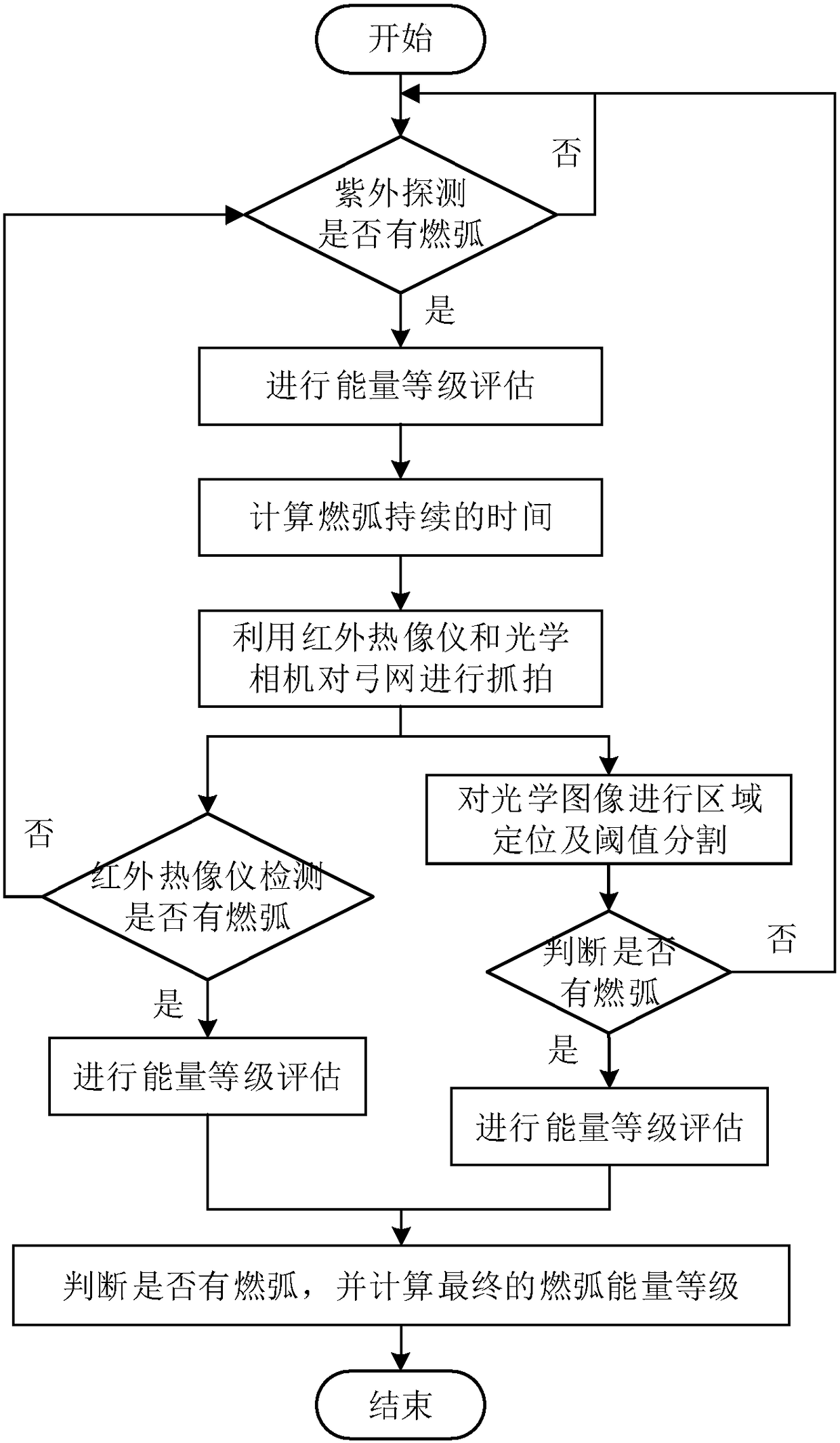
[0046] Such as figure 1As shown, an arc detection method based on the fusion of ultraviolet, infrared and optical images includes the following steps:

[0047] S1. The ultraviolet detector collects ultraviolet band signals at a frequency of 200-2000Hz (the frequency is defined according to the detection accuracy requirements, the higher the frequency, the higher the accuracy), and judges whether the ultraviolet band signals collected each time appear at 240-260nm Or between 323 and 329nm (depending on the material), if it is, it means arcing occurs; and the collected ultraviolet band signal is converted into an electrical signal V by a photoelectric sensor d , and then through digital-to-analog conversion, the voltage signal is converted into a digital signal. If arcing occurs, it is recorded as 01, otherwise it is recorded as 00, such as f...


PUM


Abstract

The invention discloses an arcing detection method based on fusion of ultraviolet images, infrared images and optical images. The method comprises the following step of S1, collecting ultraviolet bandsignals of a bow net; S2, performing energy level evaluation on arcing collected in step S1; S3, calculating the duration of arcing; S4, using a thermal infrared imager and an optical camera for capturing the bow net; S5, calculating the average temperature of the bow net in an effective area of the thermal infrared imager to determine whether or not there is arcing; S6, performing energy level evaluation on arcing detected by the thermal infrared imager; S7, performing regional positioning and threshold segmentation on the optical image; S8, evaluating the arcing energy level collected by the optical camera; S9, calculating the final arcing energy level. Detection and energy classification are conducted on arcing through the ultraviolet images, the infrared images and the optical image,whether or not there are two pieces of information including arcing and arcing energy is judged, and therefore the railway bow net and arcing of a high voltage line can be detected accurately, reliably and safely.

Description

technical field [0001] The invention belongs to the technical field of arc detection, in particular to an arc detection method based on the fusion of ultraviolet, infrared and optical images. Background technique [0002] There are four main methods for existing arc detection methods: [0003] The first is the inspection method of the inspection vehicle. This method cannot achieve real-time inspection, and the inspection must be carried out after the shutdown, which is time-consuming and laborious; [0004] The second is the contact pantograph-catenary detection method. This detection method revolves around the detection of pantograph-catenary contact pressure. The installation process is complicated, and this detection method may cause new pantograph-catenary faults when the train is running at high speed; [0005] The third is the image processing method. If this method is used alone to detect pantograph-catenary arcing, it requires a high frequency of camera acquisition ...

Claims


Application Information

Patent Timeline
IPC IPC(8): G01R31/12
CPCG01R31/1218
Inventor 方黎勇王思维
Owner 南京视道信息技术有限公司
Why Eureka
Eureka Blog
Learn More