
Method and device for determining parameters in sight tracking equipment

A technology for eye-tracking and parameter determination, which is applied in the field of eye-tracking, can solve problems such as eye-sight estimation algorithms and spot prediction algorithms, and achieve the effects of improving image processing speed, solving computational complexity, and simplifying algorithm complexity

Active Publication Date: 2018-07-27
BEIJING 7INVENSUN TECH
View PDF9 Cites 7 Cited by
  • Summary
  • Abstract
  • Description
  • Claims
  • Application Information

AI Technical Summary

Problems solved by technology

[0004] Embodiments of the present invention provide a method and device for determining parameters in a line of sight tracking device, so as to at least solve the technical problem of complicated calculations of line of sight estimation algorithms and spot prediction algorithms of line of sight tracking devices in the prior art

Method used


Image

  • Method and device for determining parameters in sight tracking equipment
  • Method and device for determining parameters in sight tracking equipment
  • Method and device for determining parameters in sight tracking equipment

Examples


Embodiment 1

[0020] According to an embodiment of the present invention, an embodiment of a method for determining parameters in a gaze tracking device is provided. It should be noted that the steps shown in the flowcharts of the accompanying drawings can be executed in a computer system such as a set of computer-executable instructions , and, although a logical order is shown in the flowcharts, in some cases the steps shown or described may be performed in an order different from that shown or described herein.

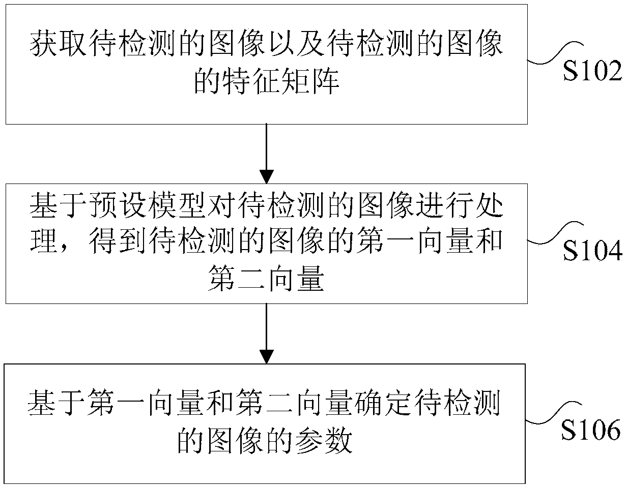
[0021] figure 1 is a flowchart of a method for determining parameters in a gaze tracking device according to an embodiment of the present invention, such as figure 1 As shown, the method includes the following steps:

[0022] Step S102, acquiring an image to be detected and a feature matrix of the image to be detected.

[0023] It should be noted that the eye-tracking devices in this application include but are not limited to VR (Virtual Reality, virtual reality) devices, AR (A...

Embodiment 2

[0068] According to an embodiment of the present invention, an embodiment of an apparatus for determining parameters in a gaze tracking device is also provided, wherein, Figure 5 is a schematic structural diagram of a device for determining parameters in a gaze tracking device according to an embodiment of the present invention, such as Figure 5As shown, the device includes: an acquisition module 501 , a determination module 503 and an estimation module 505 .

[0069] Among them, the acquisition module 501 is used to acquire the image to be detected and the feature matrix of the image to be detected; the determination module 503 is used to process the image to be detected based on a preset model to obtain the first vector and the second vector of the image to be detected Two vectors; an estimation module 505, configured to determine the parameters of the image to be detected based on the first vector and the second vector, wherein the parameters of the image to be detected i...

Embodiment 3

[0080] According to another aspect of the embodiments of the present invention, a storage medium is also provided, and the storage medium includes a stored program, wherein the program executes the method for determining parameters in the gaze tracking device in Embodiment 1.


PUM


Abstract

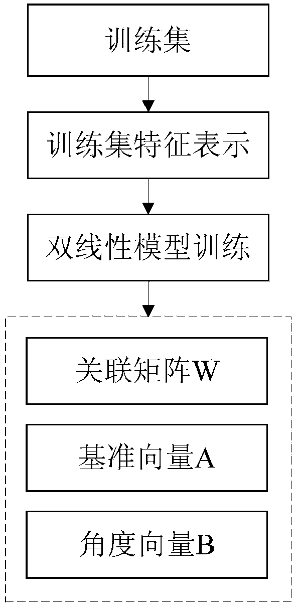
The invention discloses a method and device for determining parameters in sight tracking equipment. The method comprises the following steps of: obtaining a to-be-detected image and a feature matrix of the to-be-detected image; processing the to-be-detected image on the basis of a preset model so as to obtain a first vector and a second vector of the to-be-detected image; and determining parameters of the to-be-detected image on the basis of the first vector and the second vector, wherein the parameters of the to-be-detected image comprises at least one of positions of light spots in the to-be-detected image and sight directions of eyes in the to-be-detected image. According to the method and device, the technical problem that the sight estimation algorithms and light spot prediction algorithm of sight tracking equipment in the prior art are complex in calculation is solved.

Description

technical field [0001] The present invention relates to the field of gaze tracking, in particular to a method and device for determining parameters in a gaze tracking device. Background technique [0002] In the process of using the existing gaze tracking device, it is mainly based on the 3D approximate spherical model of the eyeball, so as to estimate the gaze point of the long-distance device according to the coordinates of the pupil center of the eyeball and corneal reflection. However, when using multiple cameras and multiple light sources, only a single point correction can complete the line of sight estimation and the matching process of the light source and the spot. However, in practical applications, the theoretical calculation of the above method for estimating the line of sight is relatively complicated, and, because the light source is not specific, the camera at some positions may not capture the image or the captured image may not be correct. As a result, the ...

Claims


Application Information

Patent Timeline
IPC IPC(8): G06K9/00G06T7/73
CPCG06T7/75G06V40/19G06V40/193G06V10/803G06F18/251G06V40/20G06V40/197G06F18/214
Inventor 刘伟王健任冬淳聂凤梅宫小虎
Owner BEIJING 7INVENSUN TECH
Learn More