Supercharge Your Innovation With Domain-Expert AI Agents!

A dc-dc circuit

A DC-DC, circuit technology, applied in the field of switching power supplies, can solve problems such as difficulty in stability, and achieve the effect of improving stability and reducing ripple

Active Publication Date: 2020-12-04
上海芯导电子科技股份有限公司
View PDF6 Cites 0 Cited by
  • Summary
  • Abstract
  • Description
  • Claims
  • Application Information

AI Technical Summary

Problems solved by technology

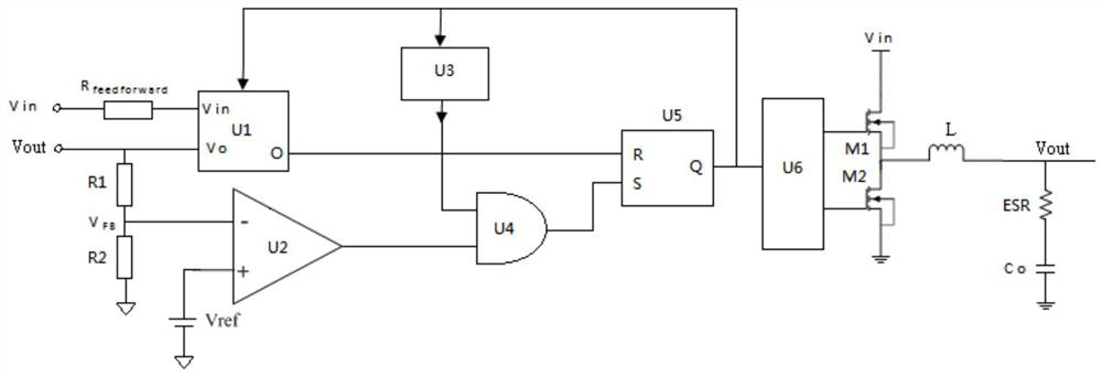
[0003] like figure 1 As shown, it is the traditional COT mode circuit diagram, which has a fast response speed, but needs to use the ESR resistor to generate a voltage ripple with the same phase as the inductor current to stabilize the loop. For occasions with extremely small ESR such as ceramic capacitors, the stability tougher

Method used


Image

  • A dc-dc circuit
  • A dc-dc circuit

Examples


Embodiment Construction

[0026] The following will clearly and completely describe the technical solutions in the embodiments of the present invention with reference to the accompanying drawings in the embodiments of the present invention. Obviously, the described embodiments are only some, not all, embodiments of the present invention. Based on the embodiments of the present invention, all other embodiments obtained by persons of ordinary skill in the art without creative efforts fall within the protection scope of the present invention.

[0027] It should be noted that, in the case of no conflict, the embodiments of the present invention and the features in the embodiments can be combined with each other.

[0028] The present invention will be further described below in conjunction with the accompanying drawings and specific embodiments, but not as a limitation of the present invention.

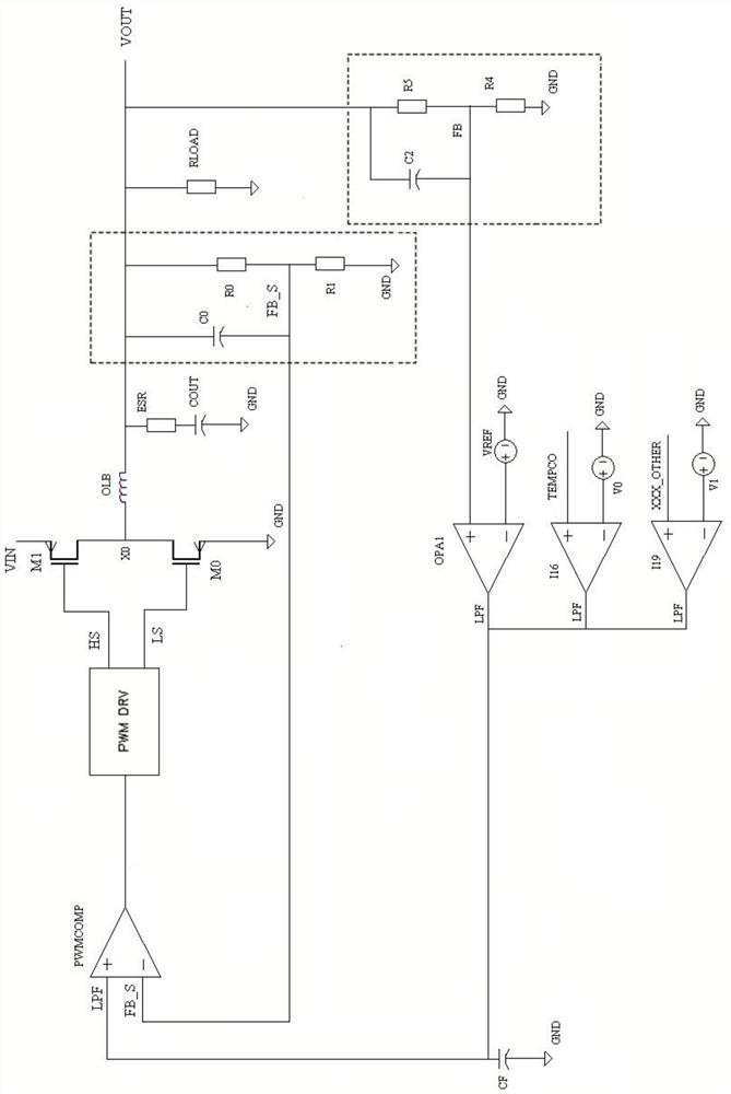
[0029] refer to figure 2 , a DC-DC circuit, specifically comprising,

[0030] an input voltage terminal (VIN)...


PUM


Abstract

The invention relates to the technical field of switching power supplies, and particularly relates to a DC-DC circuit, comprising: an input voltage end; an output voltage end; a first switching branch, controllably conducting the input voltage end and a first reference node under the action of a first driving signal; a second switching branch controllably conducting the first reference node and aground end under the action of a second driving signal; an energy storage component alternately charging or discharging during circuit operation; and a PWM signal generating unit, comparing a first voltage feedback signal sampled from the output voltage end with a voltage comparison signal to generate the first driving signal and the second driving signal, the voltage comparison signal being generated by an error amplifier, and the error amplifier being used for operating a second voltage feedback signal fed back from the output voltage end with a reference voltage. The DC-DC circuit of the invention can improve the stability of the working of a COT switch circuit and reduce the ripple of the COT output voltage.

Description

technical field [0001] The invention relates to the technical field of switching power supplies, in particular to a DC-DC circuit. Background technique [0002] DC-DC switching power supply has a variety of control modes, which can generally be divided into voltage mode and current mode according to the sampling signal. The voltage mode performs negative feedback by sampling the output voltage, and the current mode performs negative feedback by sampling the input current and output voltage; common current mode architectures include: peak current mode (Peak-Current Mode), average current mode (Average-CurrentMode) and hysteresis Current mode (Hysteretic-Current Mode); according to the duty cycle modulation method, it includes pulse width modulation (Pulse Width Modulation, PWM), pulse frequency modulation (Pulse Frequency Modulation, PFM), constant on-time mode (Constant On Time, COT), fixed off-time mode (Fixed Off Time, FOT), hysteresis control (Bang-Bang) and other modes....

Claims


Application Information

Patent Timeline
Patent Type & Authority Patents(China)
IPC IPC(8): H02M3/158H02M3/06H02M1/14
CPCH02M1/14H02M3/06H02M3/158
Inventor 符志岗肖晗朱同祥尹辉欧新华袁琼陈敏刘宗金高强
Owner 上海芯导电子科技股份有限公司
Features
  • R&D
  • Intellectual Property
  • Life Sciences
  • Materials
  • Tech Scout
  • Unparalleled Data Quality
  • Higher Quality Content
  • 60% Fewer Hallucinations
Learn More