Implementation method for state monitoring system based on CAN network topology

A technology of condition monitoring system and network topology structure, applied in transmission systems, bus networks, digital transmission systems, etc., can solve problems such as unreliability and incomplete monitoring, improve reliability, improve the level of informatization, and improve reliability. Effect

Active Publication Date: 2018-07-27
BEIJING INST OF SPACE LAUNCH TECH +1
View PDF6 Cites 2 Cited by
  • Summary
  • Abstract
  • Description
  • Claims
  • Application Information

AI Technical Summary

Problems solved by technology

[0004] In order to solve the existing problems of incomplete and unreliable monitoring of the state of the launch vehicle, the present invention innovatively provides an implementation method of a state monitoring system based on CAN network topology, which can better realize the state monitoring of the launch vehicle. The condition monitoring system effectively improves the safety and reliability of the launch vehicle, improves the informatization level of the vehicle, and thus solves many problems existing in the existing technology

Method used


Image

  • Implementation method for state monitoring system based on CAN network topology
  • Implementation method for state monitoring system based on CAN network topology
  • Implementation method for state monitoring system based on CAN network topology

Examples


Embodiment Construction

[0028] The implementation method of the status monitoring system based on the CAN network topology of the present invention will be explained and described in detail below in conjunction with the accompanying drawings.

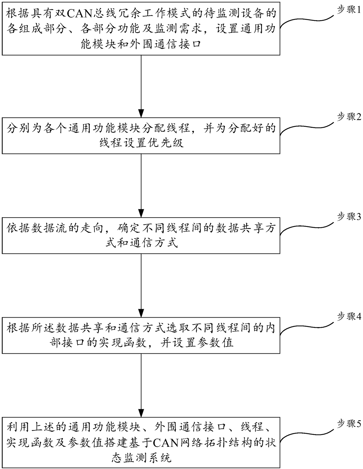
[0029] Such as Figures 1 to 6 As shown, the present invention discloses a method for realizing a condition monitoring system based on CAN network topology. This embodiment is carried out under Windows 7 operating system and LabVIEW development environment, and the method for realizing includes the following steps.

[0030] Step 1, according to the various components, functions and monitoring requirements of the equipment to be monitored with dual CAN bus redundant operating modes, set the general function module and peripheral communication interface according to the dual CAN bus redundant structure; in this embodiment, such as Figure 6 As shown, the equipment to be monitored is the ground launch support system of the launch vehicle, and the ground launch su...


PUM


Abstract

The invention discloses an implementation method for a state monitoring system based on a CAN network topology. The method comprises the following steps of 1, setting universal function modules and peripheral communication interfaces; 2, separately distributing a thread for each universal function module, and setting priorities; 3, determining data sharing modes and communication modes between thedifferent threads according to the orientation of a dataflow; 4, selecting implementation functions of internal interfaces between the different threads according to the data sharing and communication modes, and setting parameter values; and 5, using the universal function modules, peripheral communication interfaces, threads, implementation functions and parameter values to build the state monitoring system based on the CAN network topology. According to the method provided by the invention, the building of the state monitoring system of the launching platform is completed, so that the reliability, instantaneity and universality of monitoring on the launching vehicle are effectively improved, the launching vehicle state is accurately monitored during the actual using process of the launching vehicle, and the informationalized level of the whole launching vehicle is improved.

Description

technical field [0001] The invention relates to the technical field of launch vehicle control, and more specifically, the invention is a method for realizing a state monitoring system based on CAN network topology. Background technique [0002] During the execution of missions in previous launch vehicles, users sent control commands through manual control boxes and hardware control panels, and could only monitor the limited launch vehicle status through simple digital tubes and display lights, and there was a problem that it was impossible to fully monitor the launch vehicle status. problems, and communicate with all nodes on the bus through a single network segment single bus, there are problems such as high bus load rate and low reliability. In order to improve the informatization level of the launch vehicle and meet the needs of multi-point monitoring, as the number of monitoring points of the launch vehicle gradually increases, the monitoring becomes more and more diffic...

Claims


Application Information

Patent Timeline
Patent Type & Authority Applications(China)
IPC IPC(8): H04L12/26H04L12/24H04L12/40
CPCH04L12/40189H04L41/0631H04L43/08
Inventor 苏娟刘杰杨紫薇刘佑民王磊李德忠李博谢静
Owner BEIJING INST OF SPACE LAUNCH TECH
Why Eureka
Try Eureka