Juicer transmission shaft sleeve and manufacturing method thereof

A transmission shaft and juice machine technology, which is applied in household machinery for filtering food, household utensils, applications, etc., can solve problems such as heat generation, mutual wear of equipment, insufficient lubrication of transmission shaft sleeves, etc., achieve simple and convenient processing technology, and improve production efficiency effect

Pending Publication Date: 2018-07-31
常州汇丰粉末冶金有限公司
View PDF0 Cites 0 Cited by
  • Summary
  • Abstract
  • Description
  • Claims
  • Application Information

AI Technical Summary

Problems solved by technology

[0003] The technical problem to be solved by the present invention is: in order to solve the problem that the existing drive shaft sleeve is in use, an annular groove is provided on the inner wall surface of the sleeve. Insufficient lubrication inside the shaft sleeve leads to the mutual wear and heat generation between the equipment. Now a kind of fruit juice machine drive shaft sleeve and its manufacturing method are provided.

Method used


Image

  • Juicer transmission shaft sleeve and manufacturing method thereof
  • Juicer transmission shaft sleeve and manufacturing method thereof

Examples


Embodiment

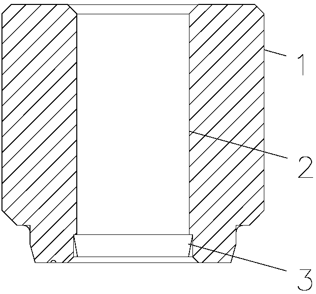
[0014] Such as Figure 1-2 Shown, a fruit juice machine drive shaft sleeve, including a body 1, the body 1 is opened with a through hole 2, the through hole 2 extends from the upper surface to the lower surface along the axial direction of the body 1, the through hole An oil storage tank 3 is opened on the inner peripheral wall of the body 2, and the cross-sectional area of ​​the oil storage tank 3 gradually decreases from the inside to the outside along the axial direction of the body 1 .

[0015] The closing slope of the oil storage tank 3 is 5° to 25°.

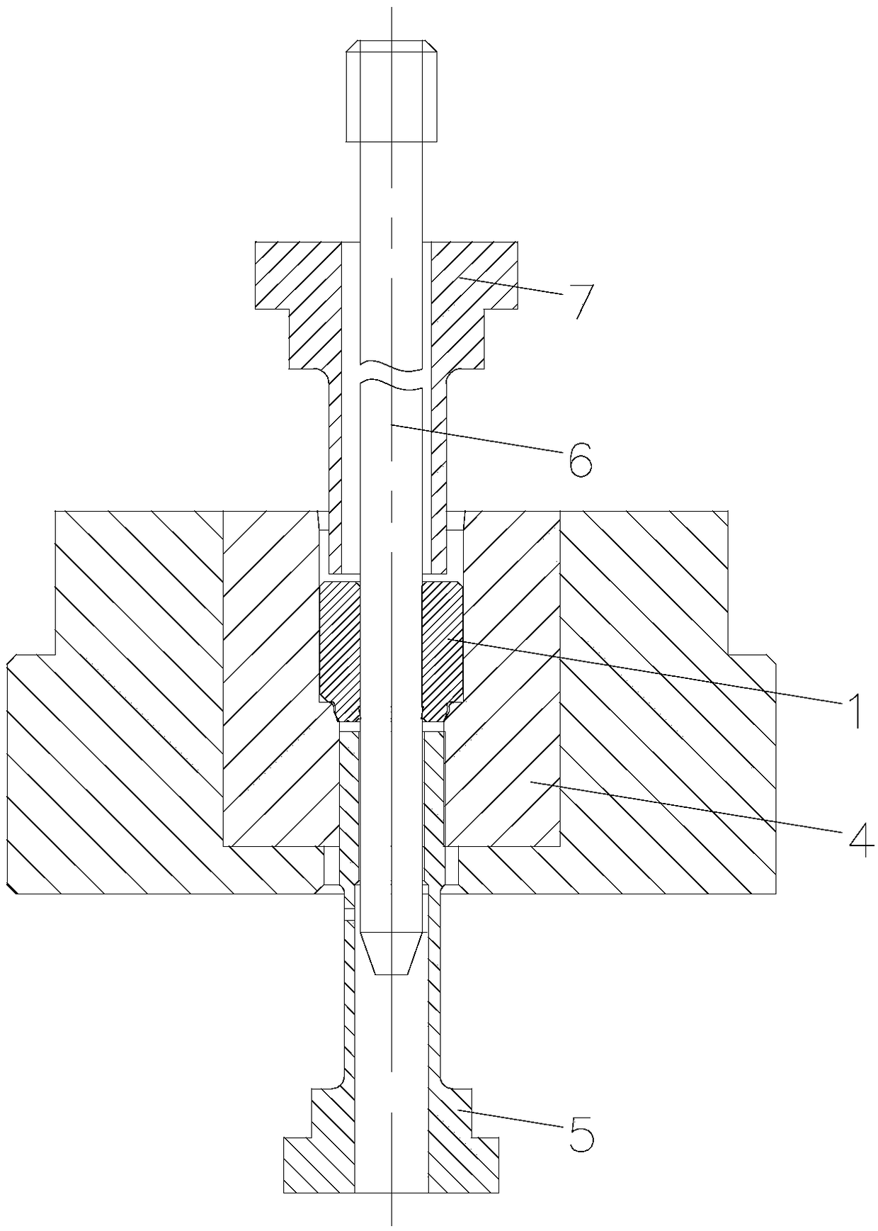
[0016] A manufacturing method for processing the above-mentioned fruit juice machine transmission shaft sleeve, comprising the following steps: S1. When stamping the fruit juice machine transmission shaft sleeve, place the fruit juice machine transmission shaft sleeve in the mold 4, and the thimble 5 on the mold 4 The top is located at the end of the oil storage tank 3 on the drive shaft sleeve of the fruit juice machine. ...


PUM


Abstract

The invention relates to the technical field of powder metallurgy equipment and particularly relates to a juicer transmission shaft sleeve and a manufacturing method thereof. The juicer transmission shaft sleeve comprises a body, wherein a through hole is formed in the body; the through hole extends from an upper surface to a lower surface in an axial direction of the body; an oil storage tank isarranged on an inner peripheral wall of the through hole; the cross sectional area of the oil storage tank is gradually reduced from the interior to exterior in the axial direction of the body. Duringuse of the juicer transmission shaft sleeve and the manufacturing method thereof disclosed by the invention, the oil storage tank is arranged on the inner peripheral wall of the through hole, and thecross sectional area of the oil storage tank is gradually reduced from the interior to exterior in the axial direction of the body, and a closing opening is formed in one end of the oil storage tank.Due to the closing opening, oil in the through hole is difficultly thrown out, the processing technology is simple and convenient, and the production efficiency of the juicer transmission shaft sleeve is improved.

Description

technical field [0001] The invention relates to the technical field of powder metallurgy equipment, in particular to a juicer drive shaft sleeve and a manufacturing method thereof. Background technique [0002] When the existing transmission shaft sleeve is in use, an annular groove is provided on the inner wall surface of the sleeve. Since the annular groove is not closed, the medium such as oil will still be thrown out, so that the internal lubrication of the transmission shaft sleeve is not enough, making the gap between the equipment Mutual wear and heat will damage the internal parts for a long time, affecting the normal operation of the equipment and reducing the service life of the equipment. Contents of the invention [0003] The technical problem to be solved by the present invention is: in order to solve the problem that the existing drive shaft sleeve is in use, an annular groove is provided on the inner wall surface of the sleeve. Insufficient lubrication insi...

Claims


Application Information

Patent Timeline
IPC IPC(8): A47J19/02
CPCA47J19/02
Inventor 石新成
Owner 常州汇丰粉末冶金有限公司
Why Eureka
Try Eureka