Laser marking method and system

A laser marking method and laser marking technology, applied in the field of laser processing, can solve the problems of high marking difficulty and low marking efficiency, and achieve the effects of reducing marking difficulty, high marking efficiency and fast marking speed

Active Publication Date: 2018-07-31
SHENZHEN TETELASER TECH CO LTD
View PDF6 Cites 15 Cited by
  • Summary
  • Abstract
  • Description
  • Claims
  • Application Information

AI Technical Summary

Problems solved by technology

[0003] Based on this, it is necessary to provide a laser marking method and system for the problems...

Method used


Image

  • Laser marking method and system
  • Laser marking method and system
  • Laser marking method and system

Examples


Embodiment Construction

[0049] In order to make the above objects, features and advantages of the present invention more comprehensible, specific implementations of the present invention will be described in detail below in conjunction with the accompanying drawings.

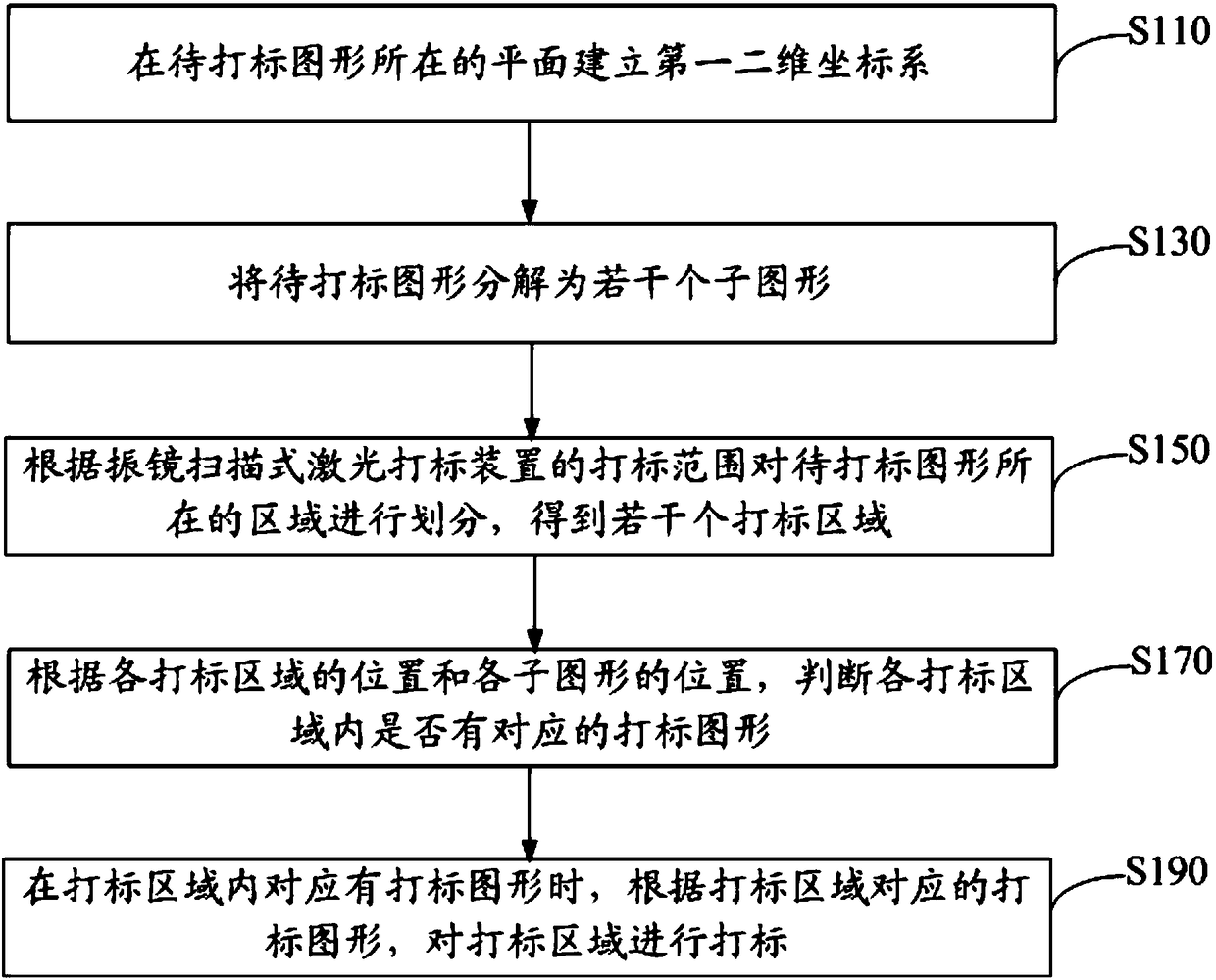
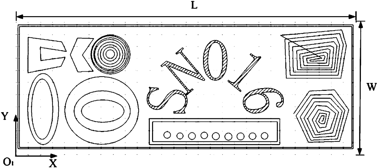
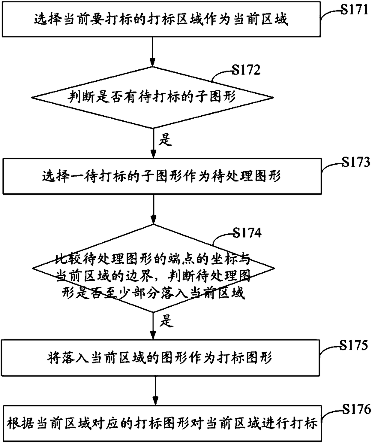
[0050] A laser marking method uses a galvanometer scanning laser marking device for laser marking. The galvanometer scanning laser marking device processes the pattern to be marked onto the surface of the workpiece. Usually, the galvanometer scanning laser marking device has a preset marking range, for example, the figure formed by the boundary of the marking range is a rectangle. Further, in this embodiment, the length of the rectangle is 20mm and the width is 20mm, that is, the boundary of the marking range forms a square. That is, the marking work of the galvanometer scanning laser marking device can only be carried out within the scope of the rectangle. In this embodiment, the laser marking method can be applied to the laser mark...


PUM


Abstract

The invention relates to a laser marking method which applies a galvanometer scanning type laser marking device for laser marking. The laser marking method includes the steps that a first and second dimension coordinate system is built in a plane where a to-be-marked graph is located; the to-be-marked graph is decomposed into a plurality of sub graphs; an area where the to-be-marked graph is located and divided according to the marking range of the galvanometer scanning type laser marking device, and a plurality of marking areas are obtained; whether each marking area has corresponding markinggraphs is judged according to the position of each marking area and each sub graph, wherein the sub graphs or part of sub graphs placed in the marking areas are marking graphs; and the marking areasaccording to the marking graphs corresponding to the marking areas are marked when the marking areas has corresponding marking graphs. The invention also relates to a laser marking system. The laser marking method and thesystem impose no limitations on the size of the to-be-marked graphs, so that the difficulties of marking are reduced, the speed of marking is accelerated and the efficiency of marking is improved.

Description

technical field [0001] The invention relates to the technical field of laser processing, in particular to a laser marking method and system. Background technique [0002] Since the galvanometer scanning laser marking system is restricted by the specifications of the F-Theta field mirror and the angle of the galvanometer, the effective marking size of the marking system is limited. When the actual graphic size is larger than the effective marking size of the galvanometer scanning, the galvanometer scanning laser marking system is difficult to mark and the marking efficiency is low. Contents of the invention [0003] Based on this, it is necessary to provide a laser marking method and system for the problem of high marking difficulty and low marking efficiency of the galvanometer scanning laser marking system. [0004] A laser marking method, using a galvanometer scanning laser marking device for laser marking; the method includes: [0005] Establish the first two-dimensio...

Claims


Application Information

Patent Timeline
IPC IPC(8): B23K26/362B23K26/70
CPCB23K26/361B23K26/70B23K26/702
Inventor 贾长桥周红林盛辉张凯周小亮颜广文欧阳志杰赵帅
Owner SHENZHEN TETELASER TECH CO LTD
Why Eureka
Try Eureka