Optical lens processing method and device, and optical lens
An optical lens and processing method technology, applied in the optical lens processing device, processing method, and optical lens field, can solve the problems of high scrap rate, lens vibration and wear, and can not satisfy users, etc., and achieve the effect of improving the grinding effect
- Summary
- Abstract
- Description
- Claims
- Application Information
AI Technical Summary
Problems solved by technology
Method used
Image

Examples
no. 1 example
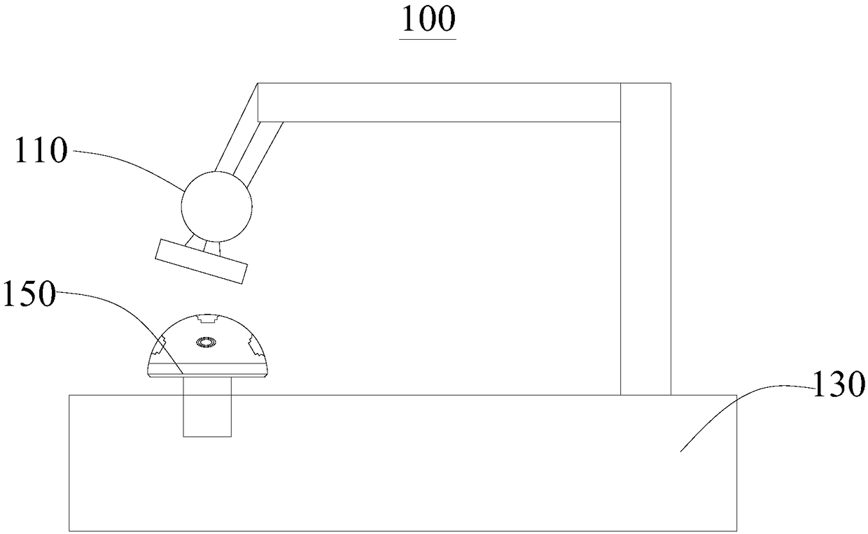
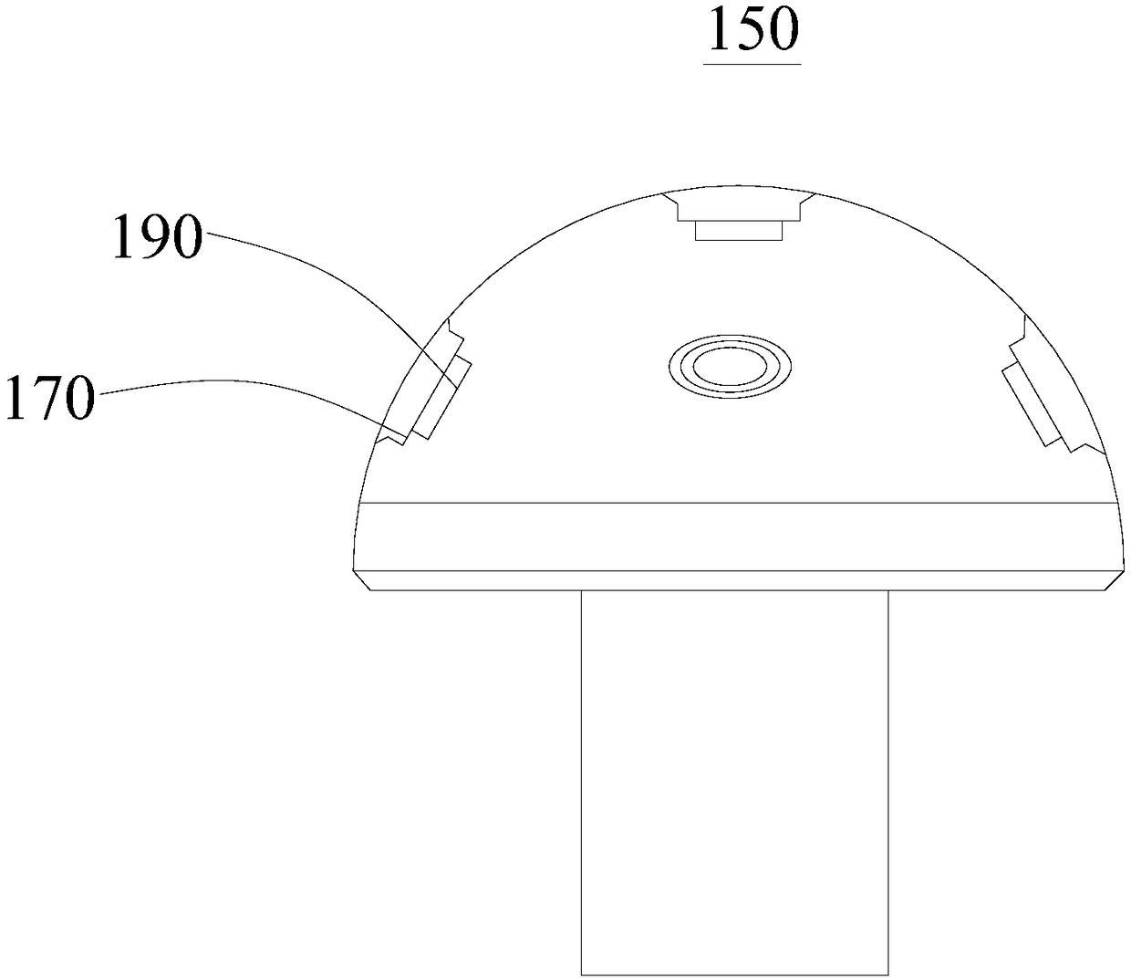
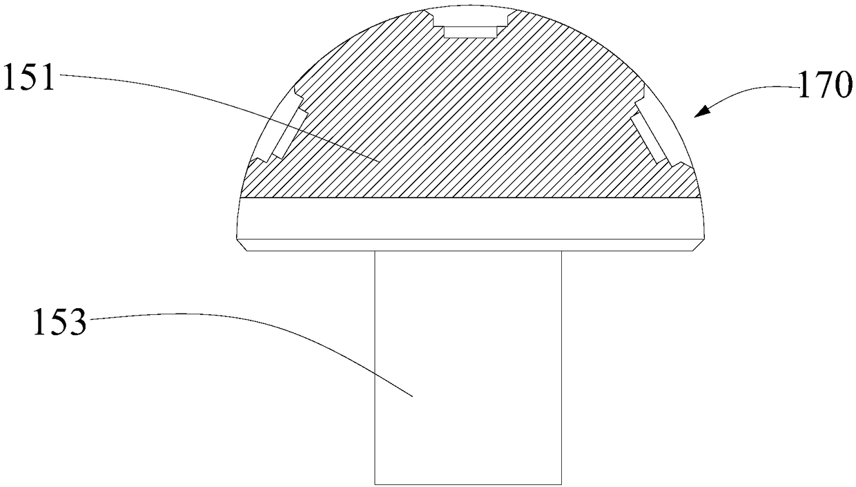
[0068] see in conjunction figure 1 and figure 2 , the present embodiment provides an optical lens processing device 100 for processing optical lenses, including a polishing machine 110, a processing machine tool 130 and a rigid disk 150, the rigid disk 150 is detachably connected to the processing machine tool 130, and the rigid disk 150 A plurality of processing slots 170 are provided for clamping the rigid mold. The rigid mold is used to fit the non-processed surface of the optical lens, and the non-processed surface is coated with adhesive. The polishing machine 110 is detachably connected to the processing machine tool 130 for grinding the processing surface of the optical lens. Specifically, the rigid disc 150 is made of rigid material, which can prevent the optical lens from shaking during processing.
[0069] In this embodiment, the rigid mold is an annular protrusion attached to the bottom of the optical lens to facilitate fixing the optical lens in the processing ...
no. 2 example
[0077] see Figure 4 , this embodiment provides an optical lens processing method, which is realized based on the optical lens processing device 100 provided in the first embodiment.
[0078] A processing method for an optical lens, which is used for processing the optical lens, the optical lens has a processed surface and a non-processed surface oppositely arranged, comprising the following steps:
[0079] S1: Apply the adhesive on the non-processed surface of the optical lens and attach it to the rigid mold.
[0080] Specifically, apply adhesive glue on the non-processed surface of the optical lens before grinding, heat the optical lens after applying the adhesive glue evenly, and attach the heated optical lens to the rigid mold, so that the optical lens and Rigid molds allow for a tight fit. In this embodiment, the optical lens is prevented from being heated on the electric heating plate during heating. Of course, other heating methods such as heating with a hair dryer m...
PUM
 Abstract
Description
Claims
Application Information
 - Generate Ideas
- Intellectual Property
- Life Sciences
- Materials
- Tech Scout
- Unparalleled Data Quality
- Higher Quality Content
- 60% Fewer Hallucinations
Browse by: Latest US Patents, China's latest patents, Technical Efficacy Thesaurus, Application Domain, Technology Topic, Popular Technical Reports.
© 2025 PatSnap. All rights reserved.Legal|Privacy policy|Modern Slavery Act Transparency Statement|Sitemap|About US| Contact US: help@patsnap.com