
Reconnaissance and defense unmanned aerial vehicle for battlefields

A UAV and battlefield technology, applied in the field of reconnaissance and defense UAVs used in the battlefield, can solve the problems of not being able to station for a long time to perform tasks and short flight time, and achieve the effects of reducing occupied space, strong environmental adaptability, and reasonable utilization

Pending Publication Date: 2018-07-31
ANHUI YUNYI AVIATION TECH CO LTD
View PDF10 Cites 5 Cited by
  • Summary
  • Abstract
  • Description
  • Claims
  • Application Information

AI Technical Summary

Problems solved by technology

With the large-scale development of UAV technology, UAVs are widely used on the battlefield for reconnaissance and defense, and can indeed play a great auxiliary role in battlefield reconnaissance and defense. Restrictions, short flight time, inability to stay on missions for a long time, and restrictions on landing sites also restrict its application.

Method used


Image

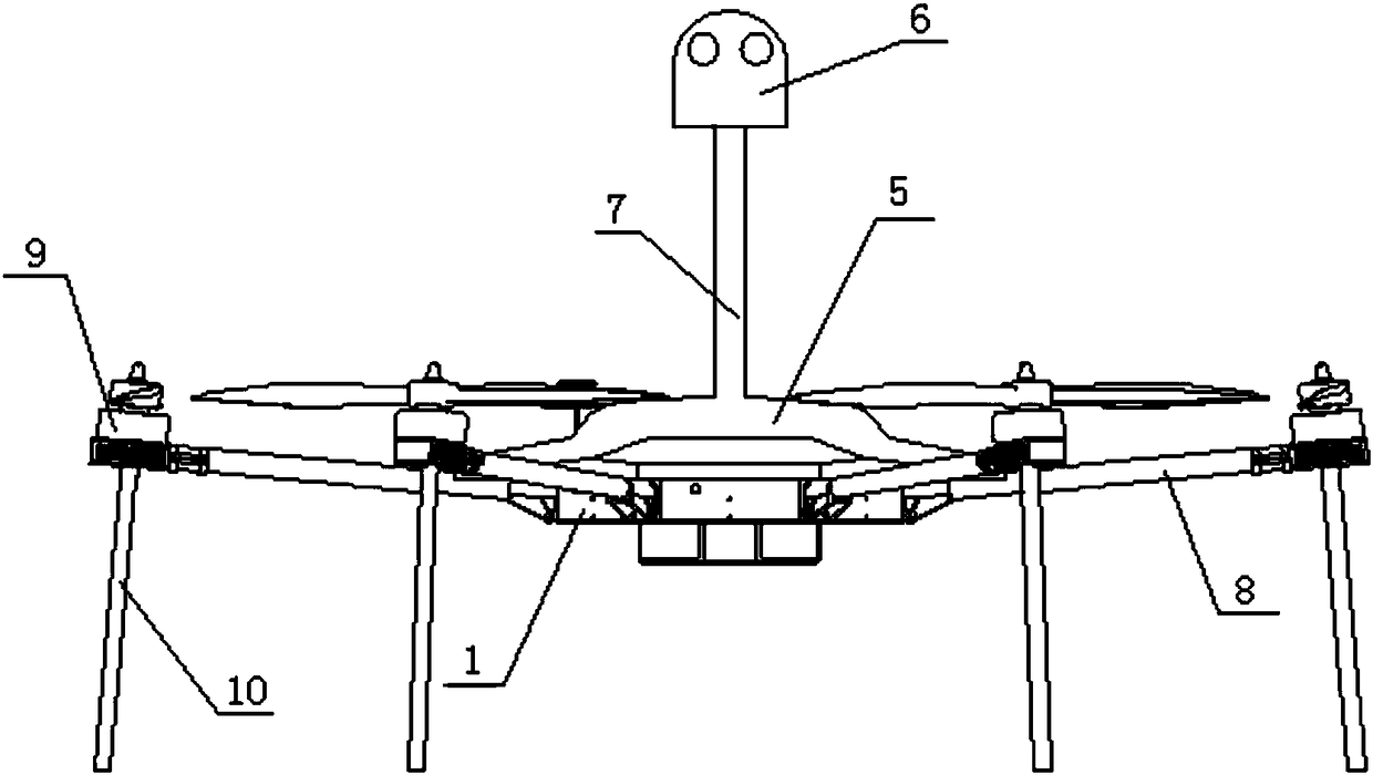
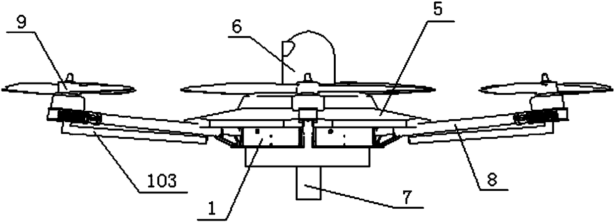
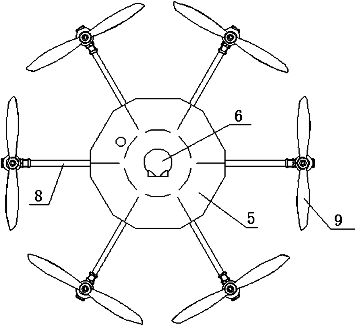
  • Reconnaissance and defense unmanned aerial vehicle for battlefields
  • Reconnaissance and defense unmanned aerial vehicle for battlefields
  • Reconnaissance and defense unmanned aerial vehicle for battlefields

Examples


Embodiment Construction

[0020] The following will clearly and completely describe the technical solutions in the embodiments of the present invention with reference to the accompanying drawings in the embodiments of the present invention. Obviously, the described embodiments are only some, not all, embodiments of the present invention. Based on the embodiments of the present invention, all other embodiments obtained by persons of ordinary skill in the art without making creative efforts belong to the protection scope of the present invention.

[0021] See Figure 1-Figure 3 and Figure 5 , a reconnaissance and defense unmanned aerial vehicle for battlefields, including a fuselage 1, a navigation flight control system 2, an electrical system 3 and an energy management system 4 arranged inside the fuselage 1, and a solar energy system arranged on the top end surface of the fuselage 1. Charging system 5, the task load 6 located directly above the fuselage 1, the lifting system 7 extending out of the fu...


PUM


Abstract

The invention discloses a reconnaissance and defense unmanned aerial vehicle for battlefields. The reconnaissance and defense unmanned aerial vehicle for the battlefields comprises an unmanned aerialvehicle body, a navigation flight control system, an electrical system and an energy management system, a solar charging system, a mission payload, a lifting system, a plurality of frames and a plurality of groups of power systems and telescopic foldable landing gears, wherein the navigation flight control system, the electrical system and the energy management system are arranged in the unmannedaerial vehicle body; the solar charging system is arranged on the end surface of the top of the unmanned aerial vehicle body; the mission payload is right above the unmanned aerial vehicle body; the lifting system extends out of the unmanned aerial vehicle body and the top end of the lifting system is connected with the mission payload; the plurality of frames are uniformly fixed on the peripheryof the unmanned aerial vehicle body; and the plurality of groups of power systems and telescopic foldable landing gears are respectively connected to the outer ends of the corresponding frames. The reconnaissance and defense unmanned aerial vehicle for the battlefields has the advantages that the environmental suitability is stronger; the flying range is long; the reconnaissance and defense unmanned aerial vehicle can garrison the battlefields and execute reconnaissance and defense missions; the unmanned aerial vehicle hides in a designated area to perform reconnaissance and defense; the solarcharging device carried on the unmanned aerial vehicle can supply power to the mission payload for a long time; the telescopic foldable landing gears can guarantee that the unmanned aerial vehicle adapts to different landing sites; and by using a ground station system to remotely monitor the unmanned aerial vehicle and send a control instruction in real time, a purpose of remote reconnaissance and defense is achieved.

Description

technical field [0001] The invention relates to the field of unmanned aerial vehicles, in particular to a reconnaissance and defense unmanned aerial vehicle used in the battlefield. Background technique [0002] Most modern wars are local wars, and the wars last for a long time, many of which are long-term stalemate tug-of-war, so a long-term uninterrupted reconnaissance and defense of the surrounding areas of the battlefield is particularly important. Traditional reconnaissance and defense equipment and means are expensive and The risks are high. With the large-scale development of UAV technology, UAVs are widely used on the battlefield for reconnaissance and defense, and can indeed play a great auxiliary role in battlefield reconnaissance and defense. Restrictions, short flight time, inability to stay on missions for a long time, and restrictions on landing sites also restrict its application. Contents of the invention [0003] The technical problem to be solved by the...

Claims


Application Information

Patent Timeline
Patent Type & Authority Applications(China)
IPC IPC(8): B64C39/02B64C25/10B64D47/00
CPCB64C25/10B64C39/024B64D47/00B64U10/10B64U50/19B64U2101/00B64U2201/20B64D27/353
Inventor 南红祥江照亮张兴宁
Owner ANHUI YUNYI AVIATION TECH CO LTD
Learn More