
Strip steel coil binding device

A technology of steel coils and straps, which is applied to packaging, bundling materials, and parts of bundling machinery, etc., which can solve problems such as lifting, unfavorable production efficiency, and increasing labor load of workers

Pending Publication Date: 2018-07-31
TIANJIN HAIGANG STEEL SHEET
View PDF7 Cites 0 Cited by
  • Summary
  • Abstract
  • Description
  • Claims
  • Application Information

AI Technical Summary

Problems solved by technology

[0002] In the existing strip steel production, after the produced strip steel is wound up, it is usually necessary to manually bundle the rolled strip steel, which increases the labor load of workers and is not conducive to the improvement of production efficiency.

Method used


Image

  • Strip steel coil binding device
  • Strip steel coil binding device
  • Strip steel coil binding device

Examples


Embodiment Construction

[0020] It should be noted that, in the case of no conflict, the embodiments of the present invention and the features in the embodiments can be combined with each other.

[0021] In describing the present invention, it should be understood that the terms "center", "longitudinal", "transverse", "upper", "lower", "front", "rear", "left", "right", " The orientations or positional relationships indicated by "vertical", "horizontal", "top", "bottom", "inner" and "outer" are based on the orientations or positional relationships shown in the drawings, and are only for the convenience of describing the present invention and Simplified descriptions, rather than indicating or implying that the device or element referred to must have a particular orientation, be constructed and operate in a particular orientation, and thus should not be construed as limiting the invention. In addition, the terms "first", "second", etc. are used for descriptive purposes only, and should not be understood ...


PUM


Abstract

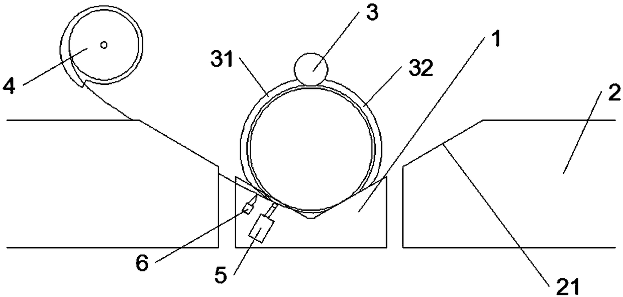
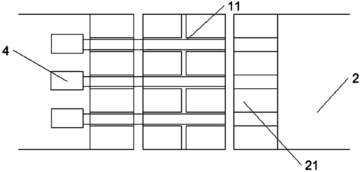
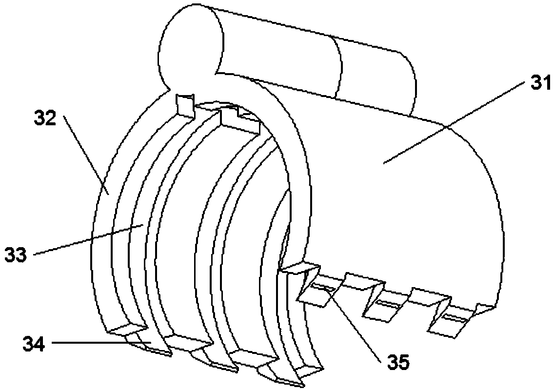
The invention provides a strip steel coil binding device. The device comprises a saddle and roller ways on the two sides of the saddle, pre-downward-sliding ways are arranged between the saddle and the roller ways, a plurality of binding belt grooves are formed in the upper surfaces of the pre-downward-sliding ways and the upper surface of the saddle, belt conveying units are arranged above one ends of the binding belt grooves, a binding belt unit capable of surrounding a strip steel coil is arranged above the saddle, a spot welding gun and a belt cutting knife are arranged at the belt feedingend of each binding belt groove in the saddle, and the spot welding guns and the belt cutting knives can penetrate through the saddle to be in contact with binding belts; and the binding belt unit comprises an arc-shaped first binding belt wall and a second binding belt wall opposite to the first binding belt wall, and the top end of the first binding belt wall and the top end of the second binding belt wall are hinged to each other. According to the strip steel coil binding device, the binding belt unit capable of surrounding the strip steel coil is adopted to cooperate with the belt cuttingknives and an electric welding machine, so that the purpose of automatically binding the strip steel coil is achieved.

Description

technical field [0001] The invention belongs to the field of strip steel production, in particular to a strip steel coil binding device. Background technique [0002] In the existing strip steel production, after the produced strip steel is wound up, it is usually necessary to manually bundle the rolled strip steel, which increases the labor load of workers and is not conducive to the improvement of production efficiency. Contents of the invention [0003] In view of this, the present invention aims to propose a steel strip coil binding device to improve production efficiency and reduce labor workload of workers. [0004] In order to achieve the above object, technical solution of the present invention is achieved in that way: [0005] A steel strip coil binding device, comprising a saddle, one end of which is connected to a roller table, a pre-glide path is provided between the saddle and the roller table, and a plurality of bindings are arranged on the upper surface of ...

Claims


Application Information

Patent Timeline
Patent Type & Authority Applications(China)
IPC IPC(8): B65B27/00B65B13/04B65B13/18
CPCB65B13/04B65B13/18B65B27/00
Inventor 于茂松孙树增李春晖
Owner TIANJIN HAIGANG STEEL SHEET
Learn More