Stator coil binding device

A wire-binding and stator technology, applied in the field of wire-binding machines, can solve the problems of undisclosed wire-binding tension, lack of necessary technical features, unclear plans, etc., and achieve high-efficiency wire-binding, practical solutions, and ingenious ideas Effect

Pending Publication Date: 2019-09-20
浙江丰源智能装备有限公司
View PDF1 Cites 0 Cited by
  • Summary
  • Abstract
  • Description
  • Claims
  • Application Information

AI Technical Summary

Problems solved by technology

[0003] The above scheme can only bind one winding coil on the stator copper coil at a time. If it is necessary to bind multiple winding coils on the copper coil at one time, it cannot be completed, resulting in low binding efficiency; at

Method used


Image

  • Stator coil binding device
  • Stator coil binding device
  • Stator coil binding device

Examples


specific Embodiment

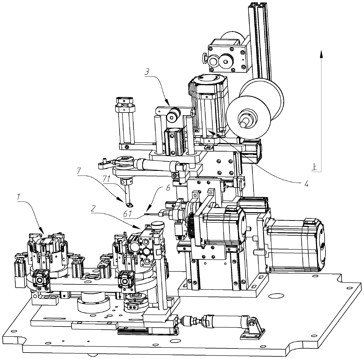
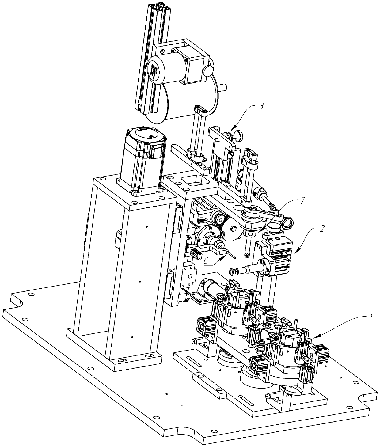
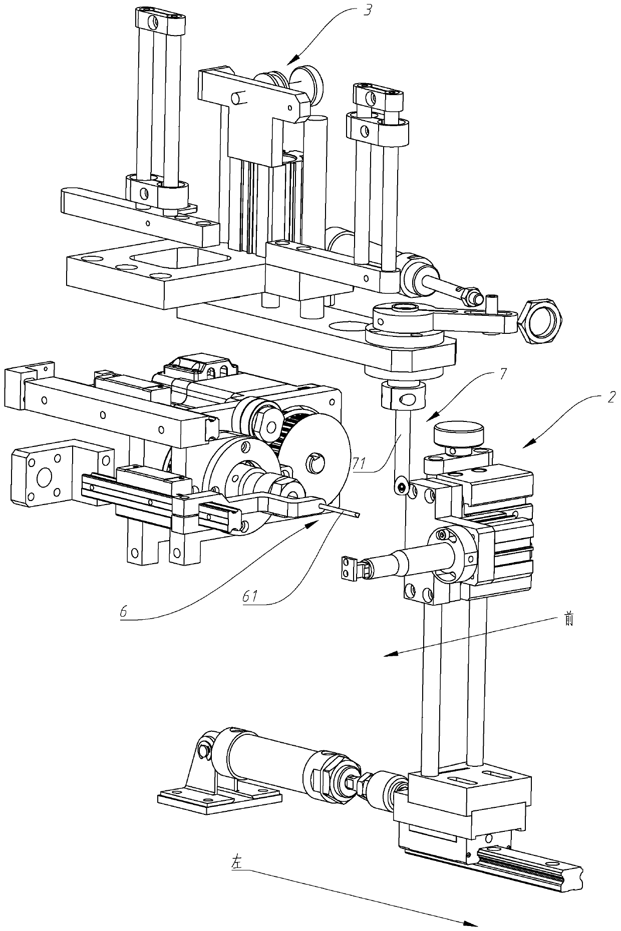
[0067] Telescopic drive source 25, front and rear drive source 26, left and right drive source 27 are air cylinders or hydraulic cylinders or magnetic cylinders. The movable ends of the telescopic drive source 25 and the front-rear drive source 26 can expand and contract along the front-rear direction, and the movable ends of the front-rear drive source 26 are fixedly connected to the fixed end of the telescopic drive source 25 . The moving ends of the left and right drive sources 27 can expand and contract in the left and right directions, and their fixed ends are fixedly connected to the fixed ends of the front and rear drive sources 26. The structure is simple and practical, and the scheme is feasible.

[0068] The thread clamping mechanism 2 of the present invention can clamp and bind the thread and cut off the tail thread of the last coil to perform the next round of thread binding. It can bind multiple coils on the same copper coil at one time, and the thread binding effi...


PUM


Abstract

The invention discloses a stator coil binding device, and belongs to the technical field of coil binding machines. An existing coil binding device can only bind a binding coil on a copper coil of a stator at a time, and if a plurality of binding coils need to be bound on the copper coil at a time, the operation cannot be finished, so that the coil binding efficiency is low. A coil clamping mechanism can clamp the binding coil and cut the tail coil part of the previous binding coil to carry out the next round of coil binding, so that the plurality of coils can be bound on the same copper coil at a time, and the coil binding efficiency is high. A fixed connection piece abuts against the edge, not provided with the coil, of the stator or/and the side wall of the stator, so that the stator is fixed; the fixed connection piece is not in contact with the coil, so that the deformation of the coil cannot be caused, and a coil hooking gap in the lower end part of the coil is not influenced; the structure is simple and practical; the scheme is feasible; the prejudice of the prior art is broken; and the conception is ingenious. A pressing piece which can abut against the binding coil is arranged on a pole in a penetrating mode; and the friction resistance provided by the pressing piece is utilized for controlling the tension of coil binding, so that a relatively stable coil binding tension force can be provided.

Description

technical field [0001] The invention relates to a stator wire binding device, which belongs to the technical field of wire binding machines. Background technique [0002] Chinese patent (Notice No. CN206743066U) discloses a motor stator wire binding device, including a binding wire up and down drive mechanism, a crochet needle advance and retreat mechanism, a crochet needle rotation mechanism, a thread head up and down mechanism, a thread head swing mechanism and a control device; The above-mentioned control device is electrically connected with the upper and lower driving mechanism of the binding thread, the advance and retreat mechanism of the hook thread needle, the rotation mechanism of the hook thread needle, the upper and lower mechanism of the thread outlet and the swing mechanism of the thread outlet. Compared with the prior art, the motor stator wire binding equipment adopts an automatic wire binding method, which obviously improves work efficiency and reduces human...

Claims


Application Information

Patent Timeline
IPC IPC(8): H02K15/00H02K15/08
CPCH02K15/0068H02K15/08
Inventor 严水祥李鹏罗潮江
Owner 浙江丰源智能装备有限公司
Why Eureka
Try Eureka