Stator coil binding mechanism

A stator coil and drive mechanism technology, applied in the direction of electromechanical devices, manufacturing motor generators, electrical components, etc., can solve problems such as very high requirements for experience and technical ability, troublesome installation and commissioning process, and hanging wires on hooks, etc., to achieve Reduce debugging and maintenance costs, reduce equipment production costs, and achieve good action consistency

Pending Publication Date: 2020-11-24
ALLIANCE AUTOMATIONSUZHOUCO
View PDF0 Cites 0 Cited by
  • Summary
  • Abstract
  • Description
  • Claims
  • Application Information

AI Technical Summary

Problems solved by technology

[0003] In the binding mechanism in the prior art, the swing of the swing mouth and the rotation of the crochet needle are respectively driven by different drive mechanisms (many belts are used for transmission), and the support shaft carrying the hook hook and the support shaft carrying the swing mouth are independent of each other. , which leads to poor coordination between the swing mouth and the crochet needle. Before the binding mechanism is used, it needs to be debugged to meet the consistent action of the two; this requires very high experience and technical ability of the installation and debugging personnel; After the belt is loose or broken, it is necessary to reinstall the belt and re-adjust the equipment. Generally, the on-site operation cannot be debugged, and it is often necessary to contact the manufacturer's professional staff for debugging, which is labor-intensive, time-consuming, and delays production. When the swing nozzle is working, it swings left and right (the support shaft of the swing nozzle is driven to rotate back and forth through the linkage mechanism, so that the swing nozzle at the front end of the support shaft swings left and right). If the swing range is too large, the insulating paper wrapped around the coil will be damaged. Breaking, this puts higher requirements on the debugging of the swing range of the swing mouth, the installation and debugging process is very troublesome and complicated, and, in the way of swinging from side to side, it is often impossible to hang the binding thread on the hook needle

Method used


Image

  • Stator coil binding mechanism
  • Stator coil binding mechanism
  • Stator coil binding mechanism

Examples


Embodiment Construction

[0022] The present invention will be described in further detail below in conjunction with the accompanying drawings and specific embodiments.

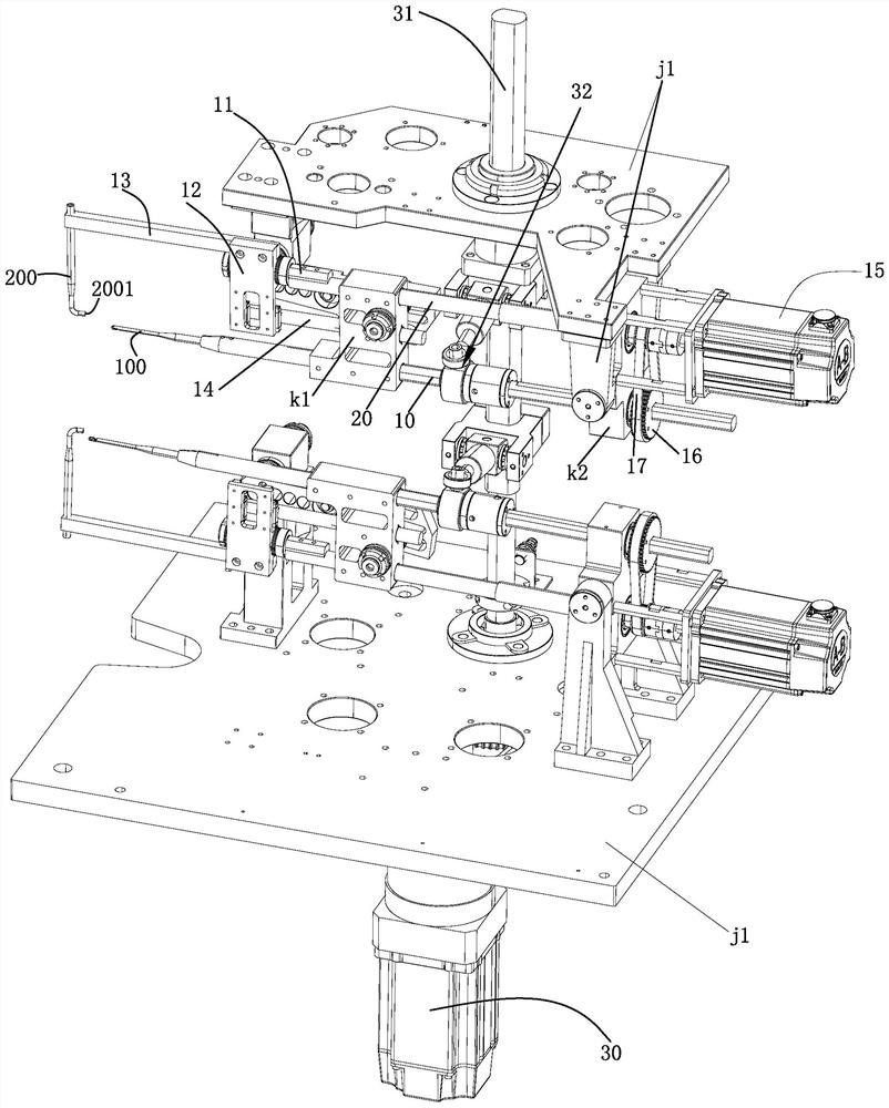
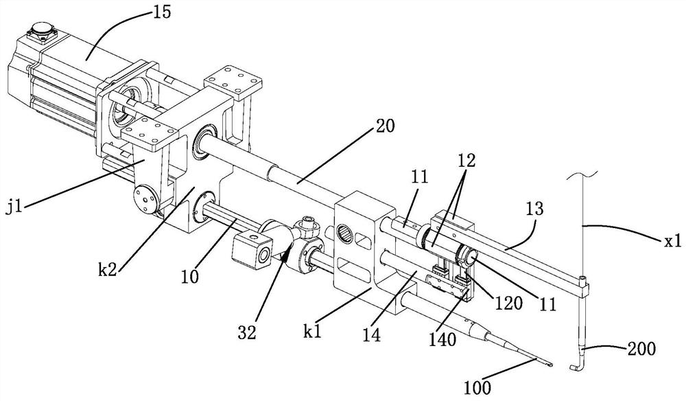
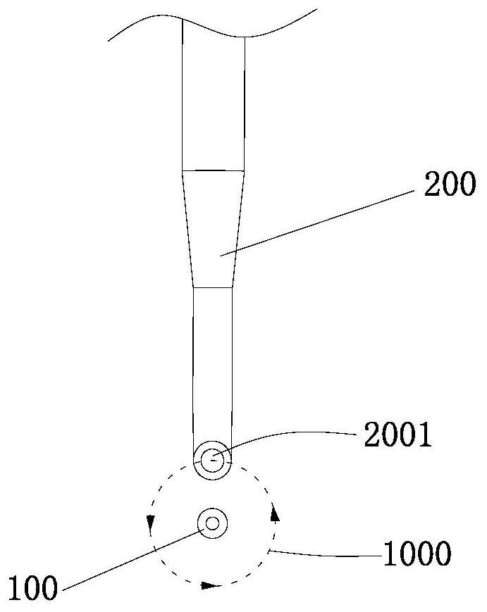
[0023] Such as figure 1 , figure 2 , image 3 As shown, a stator coil binding mechanism, the binding mechanism includes an equipment frame j1, a rotating binding unit arranged on the equipment frame j1, the binding unit includes a crochet needle 100, a swing mouth, a support assembly, and is provided on the support assembly for supporting the crochet needle The first support shaft 10 of 100, the second support shaft 20 provided on the support assembly for supporting the swing mouth, the binding mechanism also includes a first drive mechanism that drives the binding unit to rotate so that the crochet needle 100 and the swing mouth switch positions in the up and down direction 1. The second drive mechanism that drives the crochet needle 100 to move back and forth. The binding unit also includes a third drive mechanism that drives the...


PUM


Abstract

The invention relates to a stator coil binding mechanism. The binding mechanism comprises an equipment frame and a binding unit rotationally arranged on the equipment frame. The binding unit comprisesa crochet hook, a swing nozzle, a supporting assembly, a first supporting shaft arranged on the supporting assembly and used for supporting the crochet hook, and a second supporting shaft arranged onthe supporting assembly and used for supporting the swing nozzle. The binding mechanism further comprises a first driving mechanism for driving the binding unit to rotate so as to switch the positions of the crochet hook and the swing nozzle in the up-down direction, and a second driving mechanism for driving the crochet hook to do front-back telescopic motion. The binding unit further comprisesa third driving mechanism and a transmission mechanism. Only one driver for providing power for the swing nozzle and the crochet hook is arranged in the binding mechanism. Therefore, the action consistency of the two mechanisms is better, the difficulty of debugging and maintenance work is reduced, the debugging and maintenance cost is greatly reduced, the overall use stability of the binding mechanism is better, the binding efficiency of the binding mechanism is improved, the overall structure of the binding mechanism is more compact, and the manufacturing cost of equipment is reduced.

Description

technical field [0001] The invention relates to a stator coil binding mechanism. Background technique [0002] At present, the motor stator includes an iron core and a coil embedded in it. After the coil is embedded in it, in order to further stabilize the coil, the coil will be bound and fixed by a binding device. Cooperate with the swing mouth of the thread (the thread enters from the upper entrance of the swing mouth, and the thread exits from the exit of the swing mouth) to bind the coil, that is, after the swing mouth swings left and right, the binding thread coming out of the exit is hung on the crochet needle, so that The crochet needle moves forward and backward to carry out the thread binding operation. During the specific cooperation process of the two: the crochet needle extends forward to the exit of the swing mouth, the crochet needle rotates half a circle (making the hook entrance of the crochet needle face upward), and the swing mouth swings to hang the bindin...

Claims


Application Information

Patent Timeline
Patent Type & Authority Applications(China)
IPC IPC(8): H02K15/08H02K15/00
CPCH02K15/0068H02K15/08
Inventor 王袁杰
Owner ALLIANCE AUTOMATIONSUZHOUCO
Why Eureka
Try Eureka